Replacing and Adjusting the Peristaltic Pump Tubing
Pump tubing that has lost its elasticity will not deliver the sample to the nebulizer correctly. When the pump tubing appears limp or flattened, or does not require stretching to fit over the pump rollers, it should be replaced with new pump tubing.
 |
This video provides information on how to install and adjust the peristaltic pump tubing flow rate. |
There are three steps to install the peristaltic pump tubing:
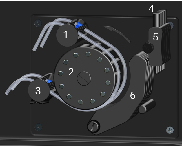
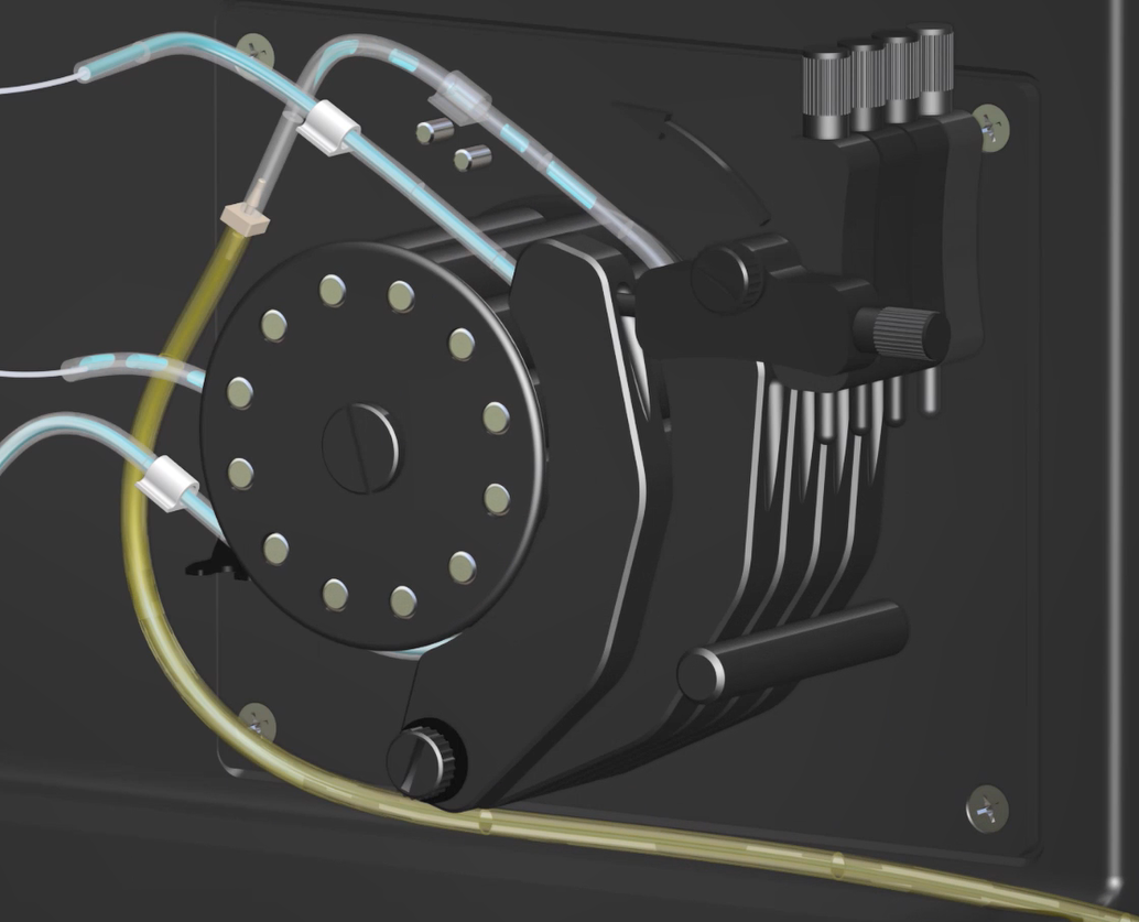
Figure 1. Peristaltic pump with arrow showing roller rotation, drain tubing clips not shown
|
1 |
Top tube retainer |
|
2 |
Pump rollers |
|
3 |
Bottom tube retainer |
|
4 |
Pressure bar tensioner screw |
|
5 |
Pressure bar tensioner |
|
6 |
Pressure bar |
Pump rollers rotate counterclockwise. Liquid delivery to the nebulizer (2 in Figure 2) and drain vessel (1 in Figure 2) occurs out the top end of the tubing. Sample uptake from the sample bottle or autosampler (4 in Figure 2) and liquid removal from the drain port of the spray chamber (3 in Figure 2) occurs in the lower end of the tubing.
The pump tubing is held in place by the pump tubing tags, which hook into the grooves on the tube retainers.
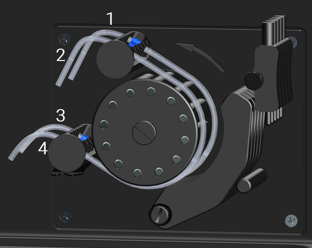
Figure 2. Peristaltic pump tubing liquid orientation
|
1 |
To the drain vessel |
|
2 |
To the nebulizer |
|
3 |
From the spray chamber drain port |
|
4 |
From the sample bottle or autosampler |
 |
The peristaltic pump has moving parts that can cause damage to hands or fingers if caught underneath the clamps during operation. Keep hands away from the peristaltic pump while it is running. |
Drain Pump Tubing
|
This video provides information on how to install and adjust the peristaltic pump tubing flow rate. |
 |
You must first install the spray chamber, then tubing, and then adjust the flow rate. |
To assemble and install the drain tubing:
|
Tubing and barb sizes (and whether a barb is needed) listed below may vary depending on the tubing and spray chamber used in the experiment. See www.agilent.com for ordering information. |
- Fit the smaller end of a 1/16 to 1/8 in (1.6 to 3.2 mm) barb to each end of a drain pump tube.
- Cut a length of PVC tubing to reach from the pump to the spray chamber.
- Fit one end over one of the barbs in the drain pump tubing.
- Cut a second piece of PVC tubing long enough to extend between the pump and the drain vessel.
- Fit one end of this over the barb in the free end of the drain tubing, as shown in the following diagram.
Figure 3. Drain pump tubing connections from the spray chamber
Where:
|
1 |
PVC tubing - 1/16 in ID x 1/16 in wall (3.18 mm ID x 1.59 mm wall) |
|
2 |
Drain pump tubing - barb and tubing sizes depend on the application requirements. |
|
3 |
PVC tubing - 1/16 in ID x 1/16 in wall (3.18 mm ID x 1.59 mm wall) |
|
4 |
To spray chamber |
|
5 |
Barb - 1/16 in ID x 1/16 OD (1.6 mm to 1.6 mm) |
|
6 |
Barb - 1/16 in ID x 1/8 OD (1.6 mm to 3.2 mm) |
|
7 |
To drain vessel |
|
For some samples, it may be necessary to select different pump tubes and/or pump speeds to optimize performance. If other sizes of pump tubing are used, alternative fittings may be required. Always ensure the drain tubing has a greater internal diameter than the sample tubing. |
- Lay the drain pump tubing from the spray chamber into the back-most channel at the top of the pump rollers with the tag inserted into the groove of the tube retainer. See Figure 1.
- Wrap the tubing around the pump rollers and place into the bottom groove of the tube retainer.
- Route the drain tubing through all three clips as shown in the image below.
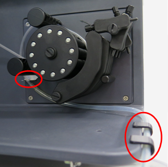
Figure 4. Peristaltic pump drain tubing clips
Solution Pump Tubing
|
This video provides information on how to install and adjust the peristaltic pump tubing flow rate. |
|
You must first install the nebulizer, then the tubing, and then adjust the flow rate. |
To assemble and install the solution pump tubing:
- Wrap the tubing around the rollers and then place it into the bottom and top tube retainer.
- Insert the solution pump tubing from the nebulizer into the top groove of the tube retainer.
- Attach a length of capillary tubing (long enough to reach the solution) to the lower end of the solution pump tubing, as shown in the following diagram and Figure 2.

Figure 5. Solution pump tubing connections
Where:
|
1 |
Solution pump tubing* |
|
2 |
Capillary tubing* |
|
3 |
Pump tubing tags |
|
4 |
To solution bottle or autosampler |
* Barb and tubing sizes depend on the application requirements.
- Place the capillary tubing in the analytical or wash solution for uptake. Alternatively, if you are using an autosampler, attach the capillary to the autosampler tubing.
|
To reduce the dead volume and maximize sample throughput, cut the excess pump tubing about 10 mm outside the tags on both ends. |
Adjusting Solution Flow Rate
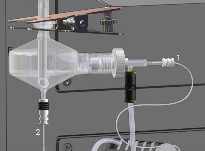
Figure 5. Solution and drain tubing
|
1 |
Sample capillary tubing from peristaltic pump |
|
2 |
Spray chamber drain tubing to peristaltic pump. |
|
This video provides information on how to install and adjust the peristaltic pump tubing flow rate. |
To ensure correct flow to the nebulizer:
- Disconnect the sample capillary (1 in Figure 5 above) from the nebulizer and place the end into a suitable container to catch the waste liquid.
- Turn on the pump.
- Push the pressure bar towards the tubing.
- Push the pressure bar tensioner down until the peg at the end of the pressure bar tensioner sits firmly against the pressure bar.
- Turn the pressure bar screw counterclockwise to release the pressure.
- Gradually tighten the pressure bar screw clockwise until the flow through the tubing is smooth.
- Turn off the pump.
|
To help see the flow, introduce some air bubbles into the capillary by lifting the sample tubing in and out of the sample bottle. |
- Reconnect the capillary to the nebulizer.
To ensure correct flow from the spray chamber drain:
- Turn on the pump.
- Push the pressure bar towards the drain tubing.
- Push the pressure tensioner down until the peg at the end of the pressure tensioner sits firmly against the pressure bar.
- Turn the pressure tensioner screw counterclockwise to release the pressure.
- Gradually tighten the pressure tensioner screw clockwise until the flow through the drain tubing is smooth.