Replacing the AVS 4, AVS 6, and AVS 7 Components
Instructions are provided below on how to:
- Remove and replace the switching valve and stator
- Remove and replace the rotor
- Replace fittings
- Replace tubing
- AVS 6 and AVS 7 tubing
- AVS 7 only: Internal standard tubing using the Internal Standard Connection Kit, G8010-60307
- Autosampler probe tubing using the Autosampler Connection Kit, G8010-60306
- Sample loop tubing using the Sample Loop, G8010-60305. Other sizes are available and the procedure is the same.
- Sample inlet kit tubing using the Sample Inlet Connection Kit, G8010-60303
- Pump tubing using the Pump Outlet Connection Kit, G8010-60308
- Nebulizer tubing using the Nebulizer Connection Kit, G8010-60304
- AVS 4 tubing
- Rinse tubing - Sample/Rinse Connection Kit, G8010-60335
- Nebulizer tubing
- Unifit nebulizers - for all Unifit type nebulizers using the Unifit Nebulizer Connection Kit, G8010-60336
- Nebulizer adaptor kit - for OneNeb nebulizers and others using the Nebulizer Adaptor Kit, G8010-60333
- Other nebulizers
- Waste tubing - Waste Tube Kit 4 Port, G8010-60334
- Sample tubing - Sample/Rinse Connection Kit, G8010-60335
- AVS 6 and AVS 7 tubing
 |
After replacing all required components, perform the Advanced Valve System test on the Instrument > Tests window. |
Component replacement intervals vary depending upon the demands of your application.
The valve has been designed so that the consumable components within the valve (the rotor and stator), can be replaced.
Unless mentioned otherwise, the instructions below apply to all three switching valves.
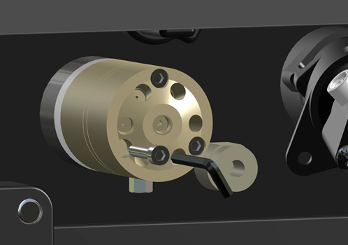
Removing and Replacing the Switching Valve and Stator on the ICP-OES
 |
This video demonstrates how to remove and replace the AVS switching valve and stator. To replace the stator, you must replace the entire switching valve body. |
  |
Chemical Hazard |
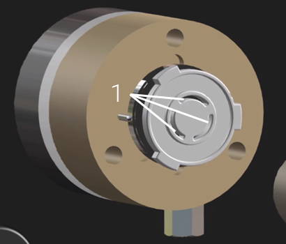
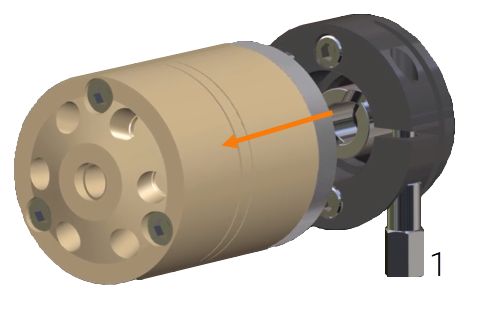
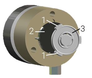
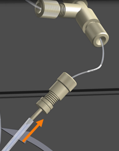
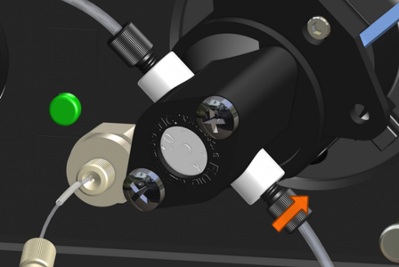
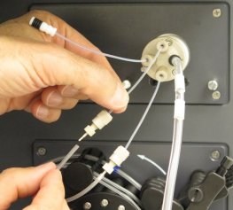
To remove the valve body/stator:
- Disconnect the tubing from the switching valve.
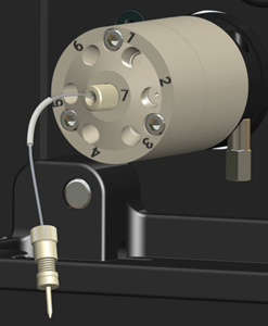
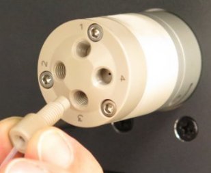
- Use the supplied 1/16 inch socket wrench to loosen the valve securing nut (1 in the image below).
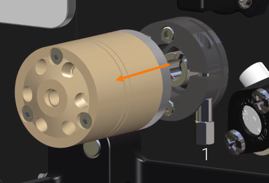
- Gently pull the valve straight out of the instrument.
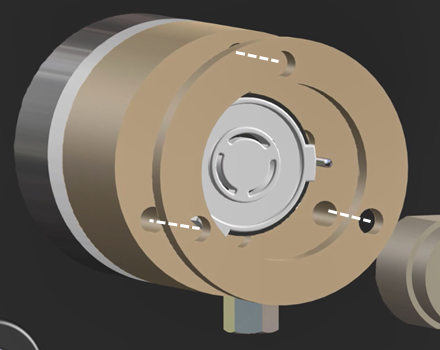
To install the valve body/stator:
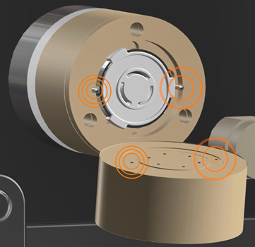
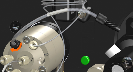
- To install the new valve/stator, match the hole labeled 'K' to the peg on the valve base. Both are indicated by the orange circles on the following image.
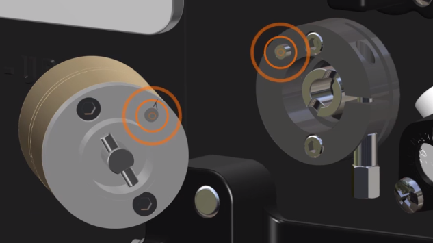
- Gently slide the valve onto the ICP-OES.
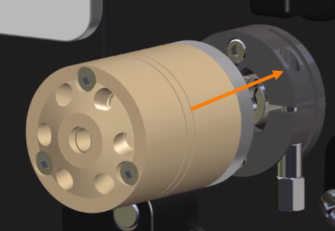
|
The valve and pin are designed so that the valve will only insert in the correct orientation. Do not force the valve. |
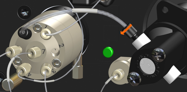
- Using the supplied wrench, tighten the valve securing nut by approximately 1/4 turn.
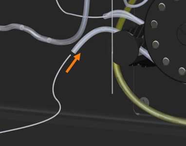
- Connect the tubing from the nebulizer, waste, autosampler, and the sample loop to the switching valve.
|
After replacing all required components, perform the Advanced Valve System test on the Instrument > Tests window. |
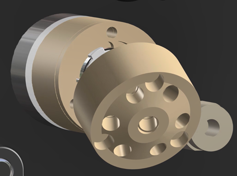
Replacing the Rotor
|
This video demonstrates how to remove and replace the rotor. |
Over time the rotor can become worn or damaged by chemicals.
| |
Chemical Hazard |
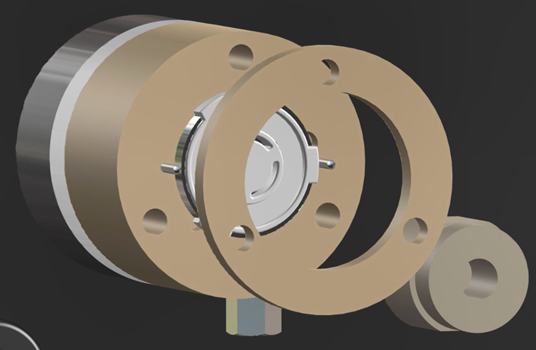
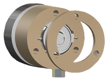
- Remove the three screws that secure the stator to the valve body using the 7/16 inch hex key provided with the valve.
- Remove the stator from the switching valve body.
- Remove the body ring off the valve body.
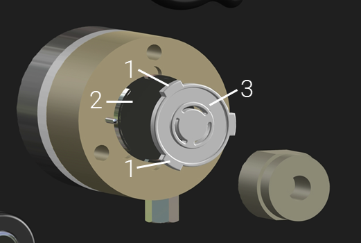
- Pull the rotor (3 in the image below) out of the driver (2) by the tabs (1).
- Wipe the driver and valve body with a soft cloth and deionized water to clean, if required.
- Clean or replace the rotor.
- Thoroughly dry before replacing the rotor and valve body.
- Insert the rotor with the liquid channel side facing out.
|
The cutouts on the driver and tabs on the rotor align so that the rotor can only go in one way. |
- Place the body ring on the valve body. Ensure that the body ring holes are aligned to the screw holes in the valve body.
- Place the stator so that the holes in the back match the alignment pins on the valve body. The screw holes should line up with the ones in the body ring and valve body.
- Insert and tighten each screw evenly in turn to ensure consistent pressure. Check that there are no gaps between the stator, the body ring, or the valve body.
- Replace the tubing onto the valve.
|
After replacing all required components, perform the Advanced Valve System test on the Instrument > Tests window. |
Cleaning the Rotor Seal, Stator and Hex Screws
| |
Chemical Hazard |
- Remove all tubing from the valve head.
- Remove the switching valve from the instrument.
- Use the supplied 1/16 inch socket wrench to loosen the valve securing nut (1 in the image below).
- Gently pull the valve straight out of the instrument.
- Remove the three screws that secure the stator to the valve body using the 7/16 inch hex key provided with the valve.
- Remove the stator from the switching valve body.
- Remove the body ring off the valve body.
- Pull the rotor (3 in the image below) out of the driver (2) by the tabs (1).
- Rinse all switching valve components with deionized water. Replace the components if damaged.
- Reassemble the valve.
Replacing Fittings
| |
Chemical Hazard |
 |
Ensure that only tubing and connectors that have an outer diameter (OD) of 1.6 mm (1/16 in.) are used or leaks may occur at the ports of the switching valve. When cutting tubing ensure that the ends are flat and do not have burrs or particulates. |
Tubing kits for the AVS 4, AVS 6, and AVS 7 come with the fittings already attached except for autosampler line. If you need to replace the fittings, always use the recommended nut and ferrule combination when replacing tubing that connects to a port on the switching valve.
The fittings supplied in the tubing kits are one piece with the nut and ferrule in one.
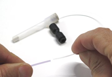
To secure unattached fittings to tubing:
- Insert the end of the tubing through the fitting and ferrule (if separate from the fitting).
-
Trim the tubing to ensure a smooth, even burr-free surface.
- If you are using a blade or scalpel, roll the tubing on a non-slip surface while slicing with the blade.
- If you are using a tubing cutter, insert the tubing into the smaller hole and then firmly squeeze the cutter handle to cut.
- Ensure that the tubing is cut square, is sitting flush to the end of the fitting.
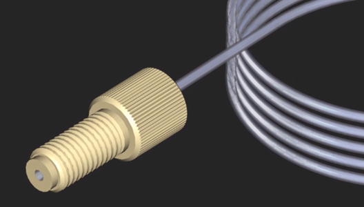
- Hold the tubing pushed against the bottom of the valve port while screwing in the fitting into an open valve port. This will ensure the tubing remains flush with the bottom of the fitting.
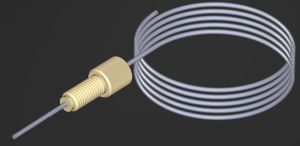
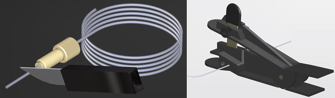
Replacing the Tubing
Always use the recommended tubing type for your application and instrumentation. Agilent supplies tubing kits preassembled with the correct fittings. Tubing that has become kinked, clogged, or damaged must be replaced.
Select from:
| |
Chemical Hazard |
|
Ensure that only tubing and connectors that have an outer diameter (OD) of 1.6 mm (1/16 in.) are used or leaks may occur at the ports of the switching valve. When cutting tubing ensure that the ends are flat and do not have burrs or particulates. |
 |
Tips More thorough mixing of the sample with diluent/IS will occur with a longer piece of tubing between the valve and the nebulizer, which ensures better replicate reproducibility, but this benefit comes at the expense of the additional time required for the sample to reach the plasma. |
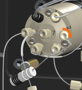
AVS 6 and AVS 7 tubing
|
This video demonstrates how to replace the AVS 6 and AVS 7 tubing. |
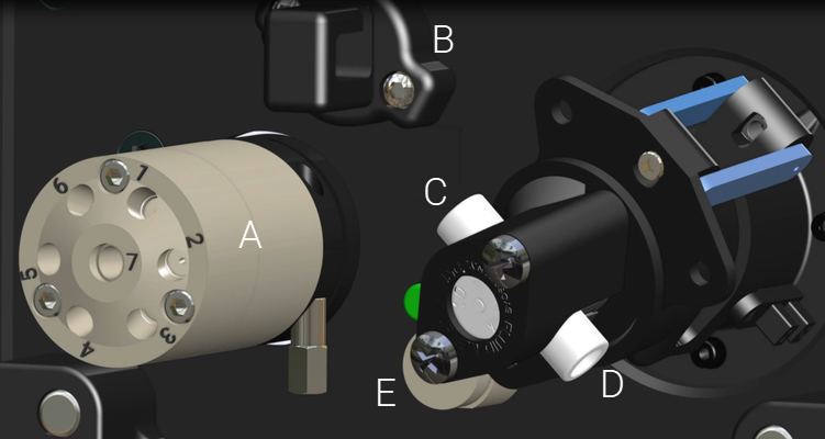
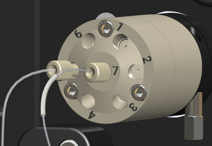
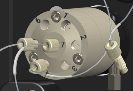
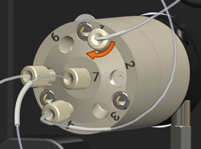
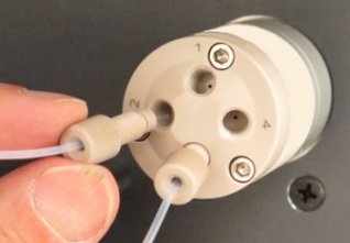
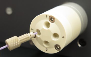
Where A is the AVS valve, B is the Sample loop holder, C is the AVS pump inlet, D is the AVS pump outlet, and E is the Bubble injector.
|
Valve port number from image "A" above |
Tubing kit part number |
Description |
|
1 |
G8010-60305 |
|
|
2 |
G8010-60304 |
|
|
3 |
G8010-60303 |
|
|
4 |
G8010-60305 |
|
|
5 |
G8010-60306 |
|
|
6 |
G8010-60308 |
|
|
7 |
G8010-60307 |
|
After replacing all required components, perform the Advanced Valve System test on the Instrument > Tests window. |
Internal Standard Connection Kit
For AVS 7 only.
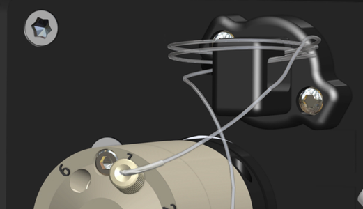
Connect the Internal Standard Connection Kit, G8010-60307. The tubing is Labeled 'Valve Port 7'.
- Connect the threaded fitting to port 7 on the switching valve.
- Insert the barbed end into the internal standard outlet tube on the peristaltic pump.
- Connect the internal standard inlet tube on the peristaltic pump to the Agilent Internal Standard container kit for AVS 7, part number G8495-60005 (or suitable alternative).
Autosampler Connection Kit
Connect the Autosampler Connection Kit, G8010-60306.
- Secure the fitting on to the autosampler probe tubing using the Replacing Fittings procedure.
- Connect the threaded fitting to port 5 on the switching valve.
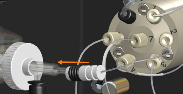
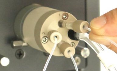
Sample Loop
Connect the Sample Loop, G8010-60305 for the supplied 1 mL loop. Other loop sizes are available.
- Connect the threaded fitting labeled "Valve Port 4" to port 4 on the AVS valve.
- Connect the threaded fitting labeled "Valve Port 1" to port 1 on the AVS valve.
- Insert the sample loop into the sample loop hook.
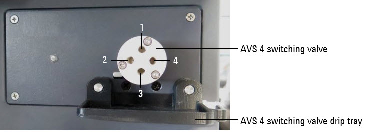
Sample Inlet Connection Kit
Connect the Sample Inlet Connection Kit, G8010-60303. This tubing kit comes assembled with three lines connected by a 'tee' piece.
To connect the Sample Inlet Connection Kit, remove the drip tray for easier access. Reinstall it once this procedure is done.
- Connect the threaded fitting labeled "Bubble Inject" to the Bubble Injection Port on the AVS assembly.
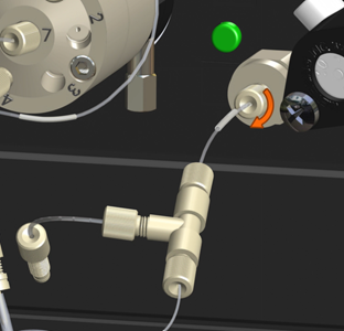
- Connect the threaded fitting on the unlabeled tubing to Port 3 on the switching valve.
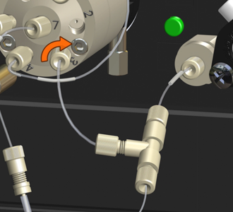
- Insert the barbed fitting on the tubing labeled "Peri Pump Rinse" into the top end of the rinse tubing on the peristaltic pump.
- Connect the rinse solution inlet tube to the bottom end of the rinse peristaltic pump tubing.
-
Insert the free end of the rinse inlet solution tube into the rinse bottle.
Pump Outlet Connection Kit
Part number G8010-60308. The kit includes two preassembled pieces of tubing.
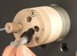
- Connect the threaded fitting labeled 'Pump Inlet Valve Port 6' to Port 6 on the switching valve.
- Connect the remaining threaded fitting on the tubing labeled "Pump Inlet Valve Port 6" to the top fitting of the AVS pump.
- Connect the threaded fitting on the tubing labeled 'Pump Outlet' to the bottom fitting on the AVS pump. Insert the free end of the tubing into the waste container bottle.
Nebulizer Connection Kit
Part number G8010-60304. Labeled 'Valve Port 2'.
|
The OneNeb nebulizer is not recommended for use with the AVS 6 or AVS 7. It may cause excessive back pressure in the sample line. If you are using a nebulizer that requires a different fitting to the one supplied with the Nebulizer Connection kit, purchase the Autosampler Connection kit, part number G8010-60306, which includes the fitting (fits 1/16 inch, 1.6 mm OD tubing) needed for the switching valve. Always ensure that the nebulizer used produces minimal sample line back pressure. Click here for more information. |
- Connect the threaded fitting on the tubing labeled "Valve Port 2" to Port 2 on the switching valve.
- Slide the black and white fitting fully onto the nebulizer.
AVS 4 tubing
|
Valve port number from image above |
Tubing kit part number |
Description |
|
2 |
G8010-60333 |
Nebulizer Adapter Kit. This kit is used with the OneNeb (as is), or in conjunction with G8010-60336 to connect a UniFit nebulizer. |
|
2 |
G8010-60336 |
|
|
2 |
|
|
|
1 and 3 |
G8010-60335 |
Sample/Rinse Connection Kit
|
|
4 |
G8010-60334 |
|
After replacing all required components, perform the Advanced Valve System test on the Instrument > Tests window. |
AVS 4 Sample/Rinse Connection Kit for the rinse tubing
Follow this procedure to connect the rinse tubing. Connect the one of the tubing pieces in the Sample/Rinse Connection Kit, G8010-60335 to port 3 on the AVS 4.
- Connect the threaded fitting to port 3 on the switching valve.
- Insert the barbed fitting into the rinse outlet line on the peristaltic pump.
 \
\
- Connect the rinse solution inlet tube on the peristaltic pump to the rinse bottle included in the Agilent Rinse and Waste Container kit, part number G8494-60005 (or suitable alternative).
AVS 4 Unifit Nebulizer Connection Kit
Connect the Unifit Nebulizer Connection Kit, G8010-60336 to port 2 on the AVS 4.
|
If you are using the OneNeb nebulizer, use the Nebulizer Adaptor Kit (G8010-60333) instead of the Unifit Nebulizer Connection Kit, G8010-60336. The flangeless fitting from the Nebulizer Adaptor Kit can be used to connect any nebulizer that uses a 1/16" OD capillary for the sample line. The tubing sleeve can be used for the connection of any nebulizer that uses a 0.042" or 1 mm OD capillary for the sample line. |
- Cut the nebulizer tubing to an appropriate length to fit between the valve and nebulizer. 100 mm is the recommended minimum.
- Follow the Assembling Flangeless Fittings and Tubing procedure to secure the fitting to the tubing.
- Connect the threaded fitting to port 2 on the switching valve.
- Slide the black and white fitting on the Nebulizer Connection Kit onto the nebulizer.
AVS 4 Nebulizer Adaptor Kit
Connect the Nebulizer Adaptor Kit, G8010-60333 to port 2 on the AVS 4.
|
Only use this kit if you are using the OneNeb nebulizer. Otherwise, use the Unifit Nebulizer Connection Kit, G8010-60336. |
- Cut the nebulizer tubing to an appropriate length to fit between the valve and nebulizer. 100 mm is the recommended minimum.
- Slide the sleeve over the OneNeb nebulizer tubing.
- Slide the threaded fitting over the sleeve and the nebulizer tubing.
- While pushing the sleeve and the capillary tubing against the bottom of the valve port, connect the fitting into port 2 on the switching valve.
AVS 4 Other nebulizers
The flangeless fitting from the Nebulizer Adaptor Kit can be used to connect any nebulizer that uses a 1/16" OD capillary for the sample line. The tubing sleeve can be used for the connection of any nebulizer that uses a 0.042" or 1 mm OD capillary for the sample line.
Always cut the capillary to appropriate length to fit between the valve and nebulizer. 100 mm is the recommended minimum.
AVS 4 Waste Tube Kit 4 Port
Connect the Waste Tube Kit 4 Port, G8010-60334, to port 3 on the switching valve.
- Connect the threaded fitting to port 3 on the switching valve.
- Insert the free end of the tubing into the waste container bottle included in the Agilent Rinse and Waste Container kit, part number G8494-60005 (or suitable alternative).
AVS 4 Sample/Rinse Connection Kit for the sample tubing
Follow this procedure to connect the sample tubing. Connect the one of the tubing pieces in the Sample/Rinse Connection Kit, G8010-60335 to port 1 on the AVS 4.
- Connect the threaded fitting to port 1 on the switching valve.
- Insert the barbed fitting into the sample outlet line on the peristaltic pump.
- Connect the sample inlet tubing on the peristaltic pump to the autosampler probe tubing.
See also: