Advanced Valve System (AVS 6 and AVS 7)
The following information is provided on this page:
For safety information and to prepare the accessory for installation, please see the instructions that came with the accessory.
About the AVS 6/7 Accessory
The AVS 6 and AVS 7 increase sample throughput and decrease turnaround time and operating costs. The switching valve is installed into the Agilent ICP-OES and is plumbed between the nebulizer and the peristaltic pump of the spectrometer. Samples are quickly loaded into the sample loop, ready for immediate analysis by the ICP-OES, greatly reducing sample uptake delays. Pre-emptive rinsing of the sample line means analysis times are reduced. The AVS 7 also features an internal tee within the valve, reducing dead volume and providing online addition of internal standard and ionization buffer solutions. A bubble injector automatically injects bubbles after the sample is loaded into the loop, isolating the sample from the rinse/carrier solution. This reduces the volume of sample required for measurement as tailing (or dilution) effects are minimized.
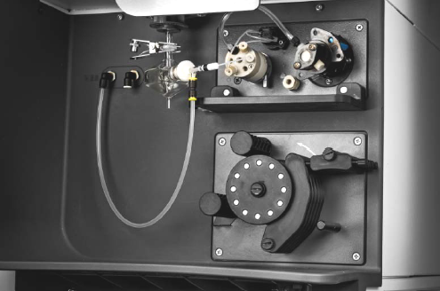
Agilent ICP-OES with the AVS 7 installed
Installation instructions
See the installation instructions that came with the switching valve.
The following maintenance instructions are here:
Using the AVS 6/7
To create and run a method using the AVS 6/7:
- Open ICP Expert.
- Create a new worksheet (or open an existing one).
- On the Configuration page enable the AVS 6/7.
- If any of the switching valve components such as tubing or rotor have been changed, run the Advanced Valve System test using a blank and the wavelength calibration solution to confirm that the %RSD is less than 2%.
- If it is not less than 2% RSD, troubleshoot the instrument precision.
- Optimize your analysis speed.
- Follow the steps on the 'Developing a Method' page, making sure to enter the optimized parameters for the AVS 6/7 on the Conditions page.
 |
Access the Instrument window to manually control the AVS 6/7, if needed. |
LED Behavior
|
State |
Condition |
LED |
|
OK - valve in inject position |
Communication is active, motors are idle or moving |
 |
|
OK - valve in load position |
Communication is active, motors are idle or moving |
 |
|
Warning |
No communication with the rest of the ICP-OES instrument, otherwise OK |
 |
|
Fault |
Firmware is unable to boot up, fault detected in the PCA |
 |
Valve diagrams
The AVS 6 and AVS 7 valves are the same with the exception of the AVS 7 having a center port for an internal standard.
For all diagrams below:
 |
Internal standard |  |
Rinse/Carrier solution |
 |
Sample solution |  |
Argon |
| Standby/start run
The valve is in the uptake position.
|
Sample uptake
The valve is in the uptake position.
|
|
A. AVS pump draws rinse into the sample loop B. Rinse drawn from the autosampler C. Rinse/carrier solution is delivered to the nebulizer by the peristaltic pump to clean the nebulizer D. Internal standard (AVS 7 only) delivered by the peristaltic pump E. Argon turned off F. The sample loop G. Rinse/carrier solution delivered by the peristaltic pump to the nebulizer. |
A. AVS pump draws sample into the sample loop B. Sample drawn from the autosampler C. Rinse/carrier solution is delivered to the nebulizer by the peristaltic pump to clean the nebulizer D. Internal standard (AVS 7 only) delivered by the peristaltic pump E. Argon turned off F. The sample loop G. Rinse/carrier solution delivered by the peristaltic pump to the nebulizer. |
| Stabilizing/reading
The valve is in the inject position.
|
After reading/rinse
The valve is in the uptake position.
|
|
A. The autosampler moves to the rinse position and the AVS pump draws rinse solution through the line to clean it B. Rinse solution is drawn from the autosampler to clean the line C. Sample is delivered into the nebulizer, from the sample loop, by the peristaltic pump D. Internal standard (AVS 7 only) delivered by the peristaltic pump E. Argon introduced from the bubble injector to help prevent sample mixing with the rinse/carrier solution F. The sample loop G. Rinse/carrier solution, delivered by the peristaltic pump, drives the sample solution out of the loop to the nebulizer |
A. AVS pump draws rinse solution to clean the line B. Rinse solution is drawn from the autosampler to clean the line C. Rinse solution is delivered into the nebulizer by the peristaltic pump to clean the nebulizer D. Internal standard (AVS 7 only) delivered by the peristaltic pump E. Argon turned off F. The sample loop G. The peristaltic pump delivers rinse/carrier solution to the nebulizer to clean it |
Switching Valve Manual Control
Open the Instrument Window. On the Status window, select the valve position, specify the AVS pump speed and turn on or off the bubble injector.
This is useful if you need to confirm whether the valve is switching positions.
Reset
The Reset button resets the valve position.
See also: