ADS 2 Tubing Installation
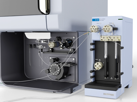 |
This video provides instructions on how to install all tubing onto an ADS 2 and the ICP-OES. Tubing replacement is required if the tubing has been damaged or when replacing the switching valve, stator or rotor. Instructions are also provided below. |
 |
Do not use a wrench to tighten fittings onto the valves. Secure the fittings finger-tight only. Always run the Advanced Dilution System 2 test after replacing tubing. |
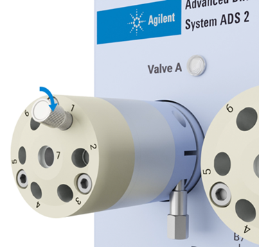
Overview
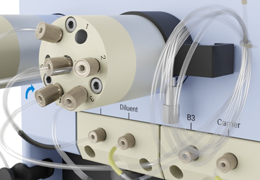
Tubing legend and instruction links:
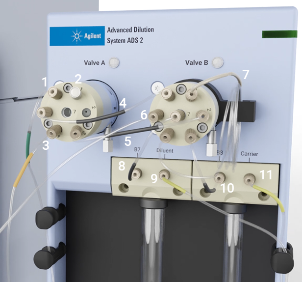
| 1. Waste flow to Valve C connection with green label tubing, part number 5005-0103 |
2. Plug, part number G8457-42001 in ports 1 and 7 (not shown) Supplied plugs will look different to those shown in this video. |
3. ADS 2 to the AVS connection with orange label tubing, part number G8457-68001 | 4. Sample flow to Valve A connection with black label tubing, part number 5005-0102 |
| 5. Diluent and carrier flow to Valve A connection with black label tubing, part number 5005-0102 | 6. From the autosampler probe | 7. Dilution loop | 8. and 10. Diluent and carrier flow connection to Valve B with black label tubing, part number 5005-0102 |
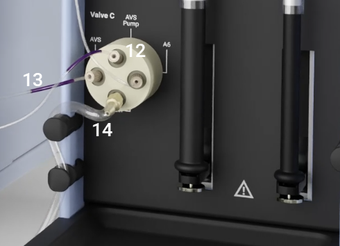
| 9. and 11. Diluent and Carrier tubing to containers with yellow label, part number 5005-0105 | 12. ADS 2 to the AVS pump connection with purple label tubing, part number 5005-0106 | 13. Waste flow from the AVS to Valve C on the ADS 2 connection with purple label tubing, part number 5005-0106 | 14. Waste tubing, part number 5005-0104, and barbed fitting, part number 5023-1517 |
Install the Plugs in Ports 1, 2 and 7
You will need 2 plugs, part number G8457-42001, and one barrier plug, part number G8457-42000.
Supplied plugs will look different to those shown in this video.
- Insert, and finger-tighten, plugs G8457-42001 in Ports 1 and 7 (not shown) of Valve A on the ADS 2.
- Insert, and finger-tighten, the barrier plug, G8457-42000, in Port 2 (not shown) of Valve A on the ADS 2.
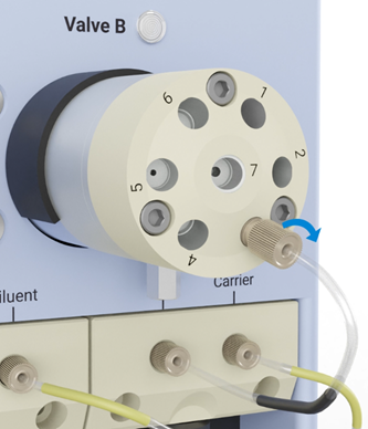
Install the Carrier and Diluent Tubing
See items 9 and 11 on the above image. You will need 2 pieces of yellow label tubing, part number 5005-0105.
- Insert, and finger-tighten, the fitting on the tubing closest to the yellow label into the port labeled Carrier on the ADS 2.
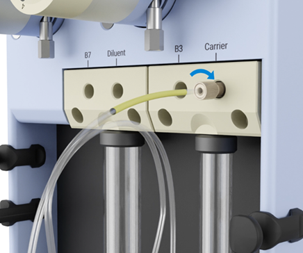
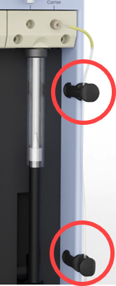
- Route the tubing through the tube clips.
- Repeat for the Diluent tubing.
- Place both tubing ends into the relevant container.
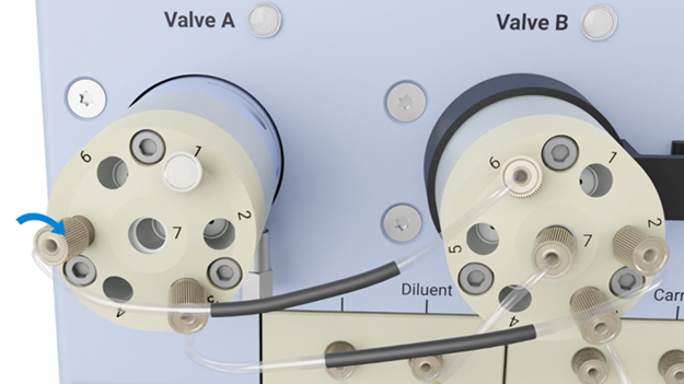
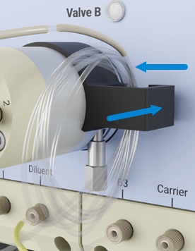
Install the Carrier and Diluent to Valve B Tubing
See items 8 and 10 on the above image. You will need two pieces of black label tubing, part number 5005-0102.
- Insert, and finger-tighten, the fitting on the black labeled tubing into the port labeled B3 on the ADS 2.
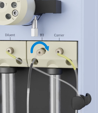
- Insert, and finger-tighten, the fitting on the free end of the black labeled tubing into port 3 on Valve B on the ADS 2.
- Insert, and finger-tighten, the fitting on the black labeled tubing into the port labeled B7 on the ADS 2.
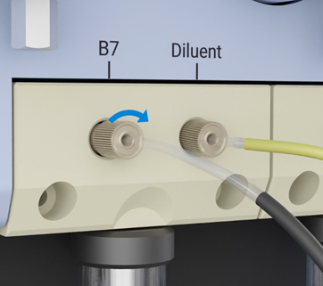
- Insert, and finger-tighten, the fitting on the free end of the black labeled tubing into port 7 on Valve B on the ADS 2.
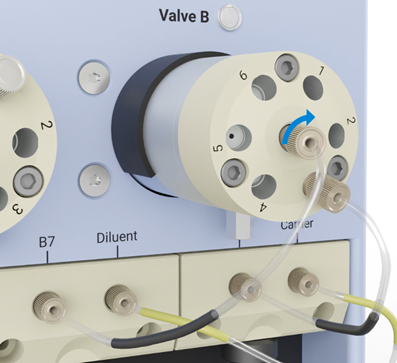
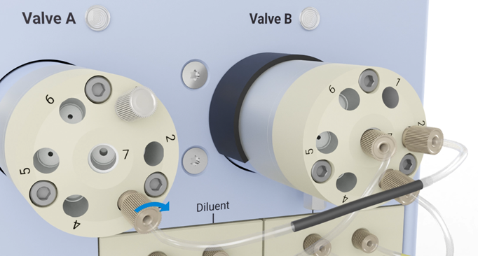
Install Carrier and Diluent Flow to Valve A Tubing
See item 5 on the above image. You will need a black label tubing, part number 5005-0102.
- Insert, and finger-tighten, the fitting on the black labeled tubing into the port 2 on Valve B on the ADS 2.
- Insert, and finger-tighten, the fitting on the free end of the black labeled tubing into port 3 on Valve A on the ADS 2.
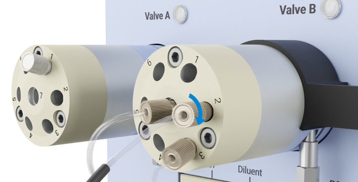
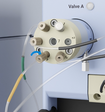
Install the Sample Flow to Valve A Tubing
See item 4 on the above image. You will need a black label tubing, part number 5005-0102.
- Insert, and finger-tighten, the fitting on the black labeled tubing into the port 6 on Valve B on the ADS 2.
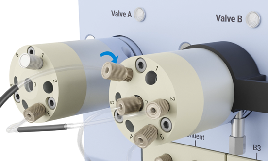
- Insert, and finger-tighten, the fitting on the free end of the black labeled tubing into port 5 on Valve A on the ADS 2.
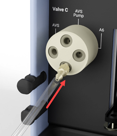
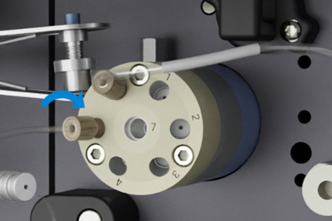
Install the Valve A to Valve C Tubing
See item 1 on the above image. You will need the green label tubing, part number 5005-0103.
- Insert, and finger-tighten, the fitting on the tubing closest to the green label into the port 6 on Valve A on the ADS 2.
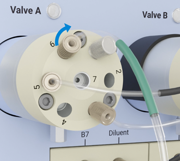
- Insert, and finger-tighten, the fitting on the free end of the green labeled tubing into the port labeled A6 on Valve C on the ADS 2.
- Route the tubing through the tube clips.
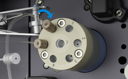
Install the Dilution Loop Tubing
See item 1 on the above image. Dilution loops can be purchased in several different sizes. See www.agilent.com for part number information.
- Insert, and finger-tighten, the fitting on the sample loop tubing into the port 4 on Valve B on the ADS 2.
- Insert, and finger-tighten, the fitting on the free end of sample loop tubing into the port 1 on Valve B on the ADS 2.
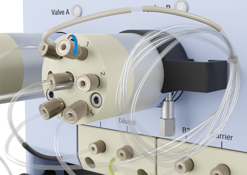
- Route the tubing through the dilution loop holder and then push the holder until it sits flush with the ADS 2 body.
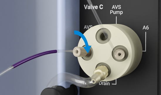
Install the Waste Tubing and Barbed Fitting
See item 14 on the above image. You will need waste tubing, part number 5005-0104, and the barbed fitting, part number 5023-1517.
- Insert, and finger-tighten, the barbed fitting into the port labeled Drain on Valve C on the ADS 2.
- Slide the tubing over the tip of the barb so that it protrudes just beyond it.
- Route the waste tubing through the tube clips.
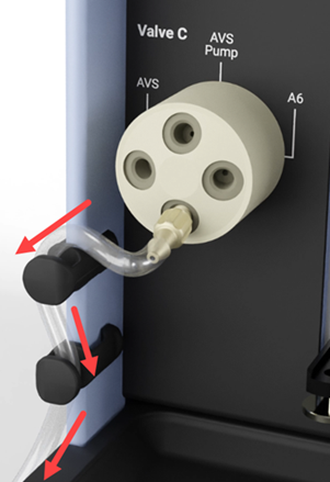
- Place the free end into the waste container. See the waste container instructions if cap assembly is required.
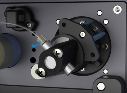
Install the ADS 2 to AVS Sample Flow Tubing
See item 3 on the above image. You will need the orange label tubing, part number G8457-68001.
- Insert, and finger-tighten, the fitting on the tubing closest to the orange label into Port 4 of Valve A on the ADS 2.
- Insert, and finger-tighten, the fitting on the free end of the orange labeled tubing into Port 5 on the AVS on the ICP-OES.
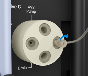
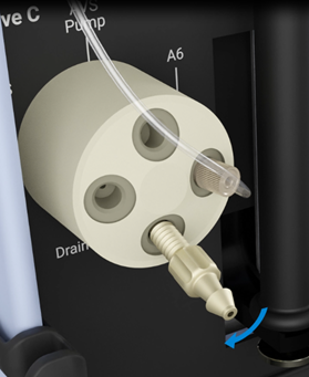
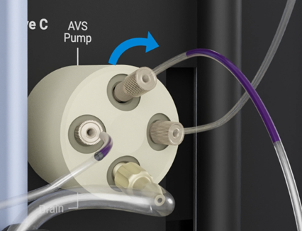
Install the ADS 2 to AVS Waste Flow Tubing
See item 13 on the above image. You will need the purple label tubing, part number 5005-0106.
- Insert, and finger-tighten, the fitting on the tubing closest to the purple label into the port labeled AVS on Valve C on the ADS 2.
- Insert, and finger-tighten, the fitting on the free end of the purple labeled tubing into the inlet end of the AVS pump on the ICP-OES.
Install the ADS 2 to the AVS Pump Connection Tubing
See item 12 on the above image. You will need the purple label tubing, part number 5005-0106.
- Insert, and finger-tighten, the fitting on the tubing closest to the purple label into the port labeled AVS Pump on Valve C on the ADS 2.
- Insert, and finger-tighten, the fitting on the free end of the purple labeled tubing into the inlet end of the AVS pump on the ICP-OES.