Advanced Dilution System 2 Troubleshooting and Method Optimization
Information on this page includes:
- About the ADS 2 test
- Before starting the ADS 2 test
- Running the Advanced Dilution System 2 (ADS 2) test
- Using AVS/ADS Timing Monitor to troubleshoot and optimize method parameters
- Delayed peak or solution introduction
- Beginning of measurement window is not flat
- Peak stops before the measurement ends
- Spike in the signal at the start of the measurement peak
- Very delayed stable peak
- Very delayed unstable peak
- Intensity gradually increases over the read time
- No signal appears during measurement
- Slow peak decline
- Peaks fluctuate during the time scan
- Low unstable signal
About the ADS 2 Test (ADS 2)
This test performs 3 fixed dilutions of 2x, 10x and 100x of a 5 ppm Mn standard solution (included in the ICP-OES wavelength calibration solution) and then checks that the concentrations are within a +/-10% tolerance. The test is run from the 'Tests' tab in the 'Instrument' window.
 |
The autosampler is required for this test. Place the solution in the specified location found on the Autosampler and Sequence pages. |
Before Starting the Advanced Dilution System 2 Test
- Ensure the torch, nebulizer, spray chamber, and pump tubing are clean, in good working condition, and installed on ICP-OES
- Use a 1.4 mm injector for Radial views or a 1.8 mm injector for Dual view
- The external instrument exhaust and instrument are turned on
- The ICP Expert software is open
- Wavelength calibration solution must be available
- A 1% nitric acid (analytical reagent grade) Blank and Rinse solution should be prepared using de-ionized water
- Ensure the instrument is powered on, with the cooling water connected and flowing, and the boost gas purge enabled for at least 2 hours before performing the test
- Plasma should be on for at least 10 minutes before testing
- The instrument calibration (wavelength calibration) and the detector calibration (dark current scan) must be valid
- Check in File > Options > Preferences that the default Standards rack selected matches the configuration of your selected autosampler
- For Agilent SPS 4 autosamplers, check that the correct standards rack is selected (either the 34-tube rack or 5-tube rack)
Running the Advanced Dilution System 2 Test
- Click Instrument on the ICP Expert toolbar.
- Click the Tests tab.
- Deselect all tests except Advanced Dilution System 2 Test.
- Load the Blank and Standard in the Standards Rack at positions 1 and 2 respectively.
- Click Run Tests.
- The method parameters are automatically filled in when the test begins.
To print the report, click the print button in the top left corner of the print preview display.
Using AVS/ADS Timing Monitor to Troubleshoot or Refine Method Parameters
Instructions on how to run the AVS/ADS Timing Monitor are found here.
Start with the parameters defined in the AVS Accessory on the Conditions page. Then adjust time or flow rates as needed when troubleshooting or refining method parameters.
Below are several AVS/ADS Timing Monitor scans with a list of ways to resolve the indicated issues. Compare your peak shapes with these to refine your method parameters or to resolve issues. Show me what a 'good' AVS/ADS Timing Monitor scan looks like.
Delayed Peak or Solution Introduction
| Cause | Action |
| The Pump Rate - Uptake is too low. The solution is not delivered fast enough to fill the sample loop. | Increase the Pump Rate Uptake. |
| The Valve Uptake Delay is too low. The time required for the solution to pass from the autosampler to the switching valve is too short which prevents enough solution to get to the valve before fill the sample loop. | Increase the Valve Uptake Delay. When an ADS 2 is enabled, additional time is automatically added to compensate for the extra tubing. |
| The AVS sample loop and the ADS 2 dilution loop are not the same size or the loop size parameter is set incorrectly. | Both loops must be the same size. Change the loop on the ADS 2 or ICP-OES. Configure the loop size in the software. |
| Air is present in the tubing. | Prime the lines to flush the system. Run the AVS pump to introduce solution into the tubing. |
Timing Monitor examples
- Delayed peak at the start of Condition Set 1. The starting peak should be sharper like the one shown in Condition Set 2.
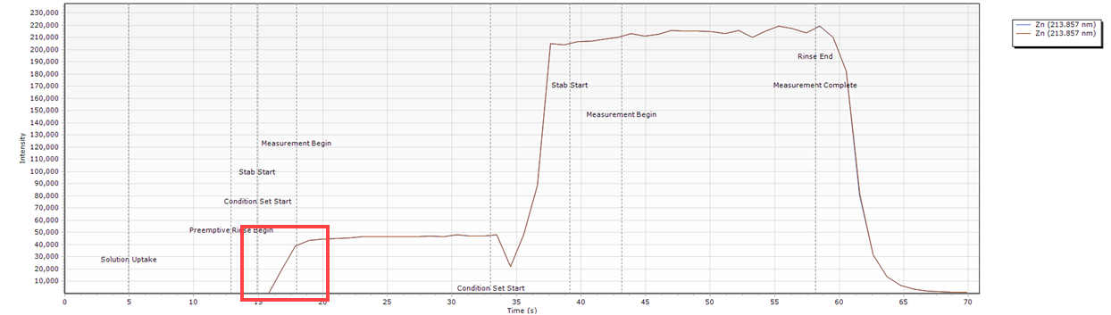
- The loop is half full. This will result in a solution other than the sample being delivered to the plasma during the measurement step.
What condition sets were used for this example?
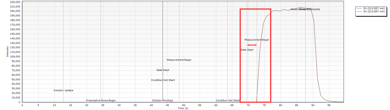
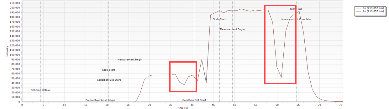
Beginning of Measurement Window is not Flat
| Cause | Action |
| The Stabilization time is too low. The plasma needs longer to equilibrate after sample introduction. | Increase the Stabilization time on the Conditions page. |
| An element in the solution is 'sticky'. This could be due to the sample matrix and rinse setup. | Increase the Stabilization time or use an alternative sample preparation procedure. Investigate the other elements in your solution. If only one seems to carry over when compared to the rest then change the rinse solution or increase the rinse time. |
Timing Monitor examples
- A peak occurs at the start of the measurement. This can indicate that the stabilization time is not long enough.
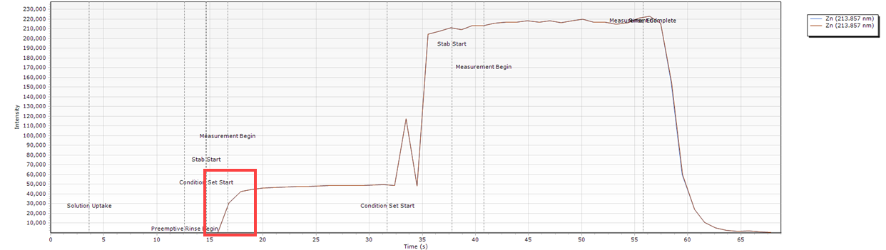
- Slow sample introduction resulting in a curved peak at the start of the measurement.
What condition sets were used for this example?
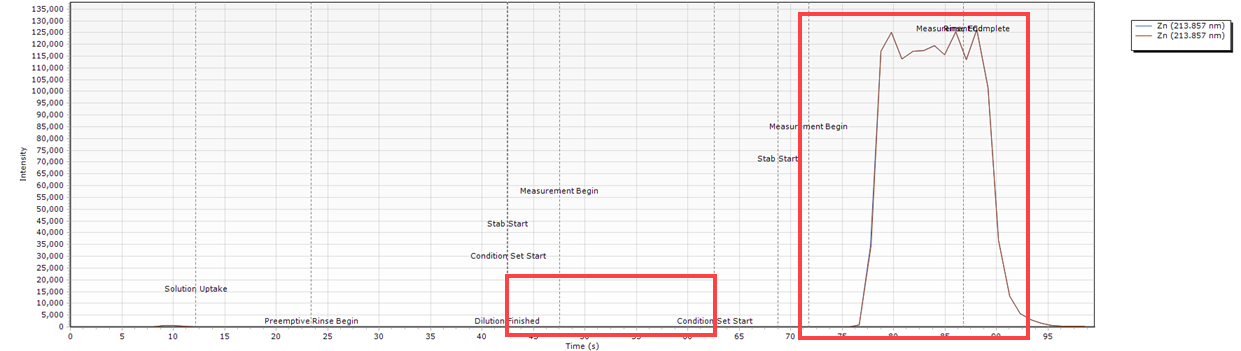
Peak Stops Before the Measurement Ends
| Cause | Action |
| Insufficient sample for the analysis time set in the method conditions. | Optimize the Stabilization time. Adjust the Read time on the Conditions page. Adjust the flow rates in the Condition Sets on the Conditions page. Increase the loop size in the software. Adjust the peristaltic pump speed and/or pressure bars. |
Timing Monitor examples
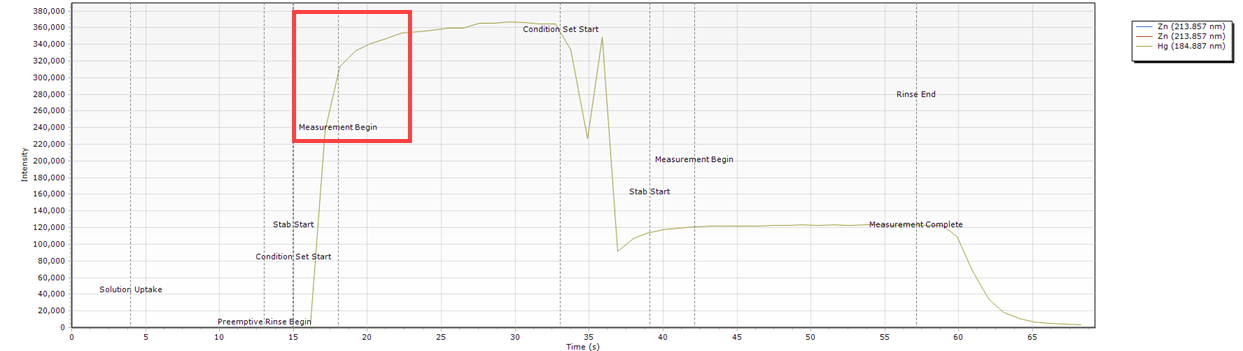
- The peak ends before the measurement does. This can indicate that the stabilization time too long or flow rates are too high.
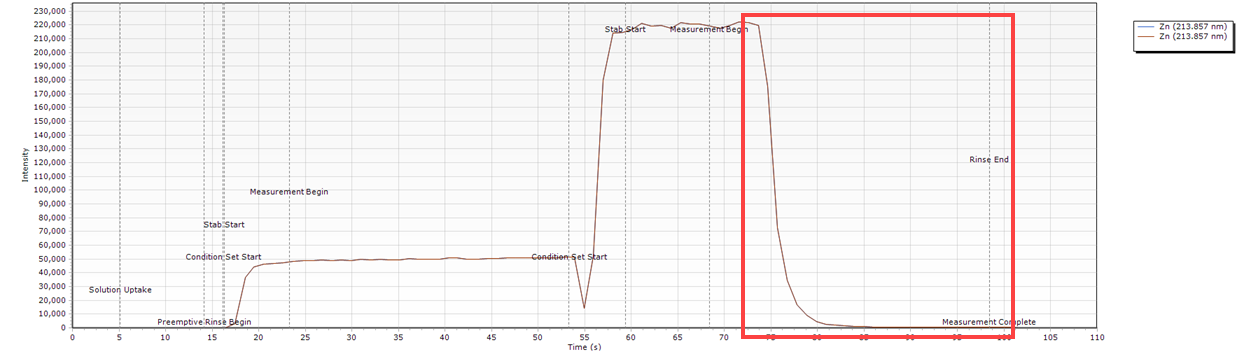
What condition sets were used for this example?
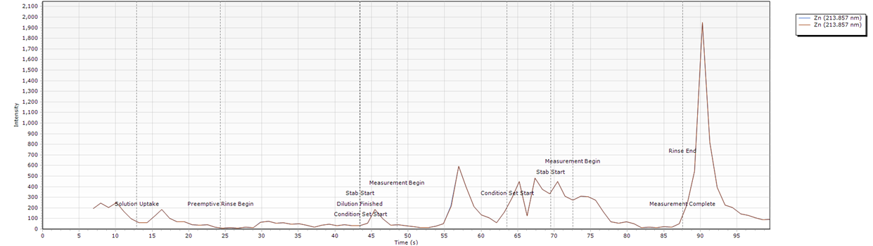
Spike in the Signal at the Start of the Measurement Peak
| Cause | Action |
| Loose syringe fitting at the valve port or syringe not installed correctly. | Check the diluent and carrier solution connections. Check that the syringe is installed correctly. |
| The diluent is low/empty. | Check the diluent container and fill if necessary. If you are using a sinker, check that liquid flow is smooth and consistent. |
Timing Monitor examples
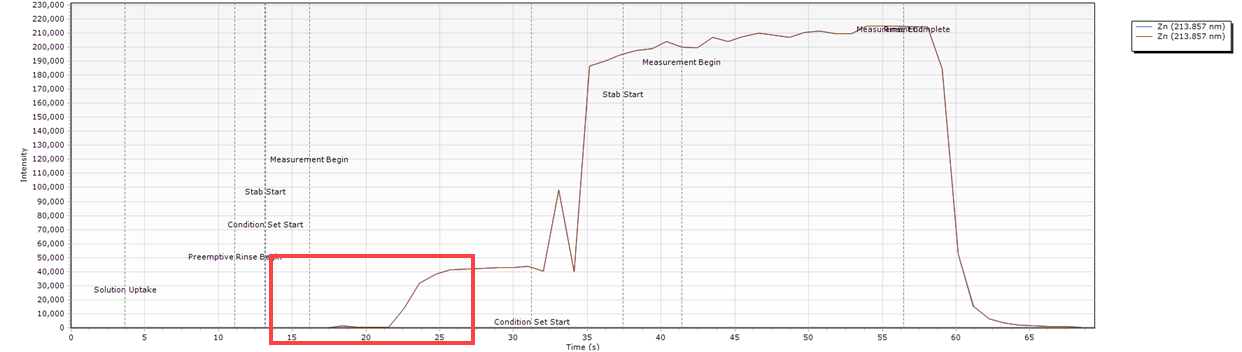
- The peak spikes and then settles. Both peaks indicated here have a higher peak height at the start of the measurement than near the end of the measurement.
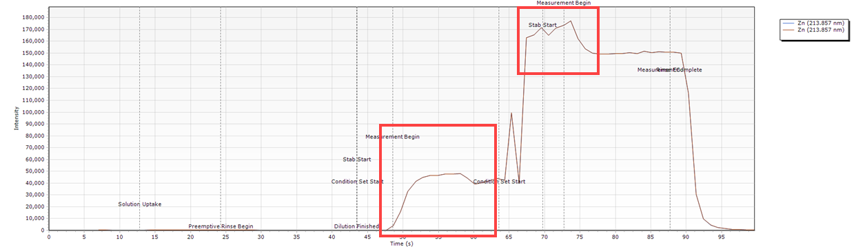
- There is no peak in the first Condition set measurement because there was no diluent or carrier solution to push the sample through to the AVS. The large spike in the appears in the second condition set measurement is caused by diluent or carrier solution running out halfway through the sample delivery.
What condition sets were used for this example?
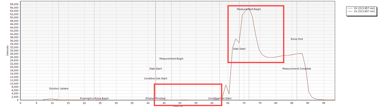
Very Delayed Stable Peak
| Cause | Action |
| The diluent is low/empty. | Check the diluent container and fill if necessary. |
Timing Monitor examples
- There is a delay between the stabilization starting and the peak appearing. The sample is not delivered at all in the first condition set and is delayed in the second condition set.
What condition sets were used for this example?
Very Delayed Unstable Peak
| Cause | Action |
| The carrier solution is low/empty. | Check the carrier container and fill if necessary. |
| The carrier syringe is loose at the port. | Check the diluent and carrier solution connections. Check that the syringe is installed correctly. |
Timing Monitor examples
- There is a long delay before the peak appears. The sample is not delivered at all in the first condition set and is delayed and unstable in the second condition set.
 What condition sets were used for this example?
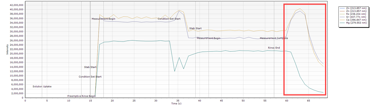
Slow Peak Decline
| Cause | Action |
| The an element in the solution is 'sticky'. This could be due to the sample matrix or rinse setup. | Increase the rinse time to minimize impact on subsequent samples. Change the rinse solution. |
| Conditions have changed after a rinse completes | Investigate the other elements in your solution. If only one seems to carry over when compared to the rest then change the rinse solution or increase the rinse time. |
Timing Monitor examples
- The signal does not wash out during the allocated rinse time.
What condition sets were used for this example?
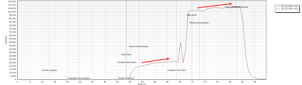
Intensity Gradually Increases Over the Read Time
| Cause | Action |
| The carrier solution is low/empty. | Check the carrier container and fill if necessary. |
| Instrument still warming up or purge has not completed yet. | Instrument warm up can take 20 minutes. If you are using wavelengths below 189 nm, purging can take several hours. Polychromator thermal stabilization can also take several hours when starting up from a long term shutdown. |
Timing Monitor examples
- The intensity increases over time for both condition sets.
What condition sets were used for this example?
No Signal Appears During Measurement
| Cause | Action |
| Incorrect plumbing of the sample introduction system | Confirm that the tubing used is correct and also connected in the correct location on the ADS or ICP-OES. How do I connect my ADS 2 tubing? How do I connect my AVS tubing? How do I connect the sample introduction system tubing and components? |
| Loose connections of the sample introduction tubing | Check that all connections on the ADS 2, AVS and ICP-OES are tight. Important: Finger tighten the fittings only. Do not use a tool to tighten the tubing. |
| Incorrect loop size is configured in the ADS 2 settings. | In ICP Expert, click Instrument > Configuration. Select the correct Loop Volume from the drop-down menu. Important: Both the AVS and ADS 2 loops must be the same size. |
| AVS/ADS loops are not filled. | Check that the Pump Rate - Uptake and Valve Uptake Delay flow rates are high enough to fill the loop on the Conditions page. |
Timing Monitor examples
- There is no signal during measurements.
What condition sets were used for this example?
Peaks Fluctuate During the Time Scan
| Cause | Action |
| Air bubbles are present in the solution. | Check for air leaks. Check that the Pump Rate - Uptake and Pump Rate - Inject rates on the Conditions page aren't too high. |
Timing Monitor examples
- The intensity is not consistent.
What condition sets were used for this example?
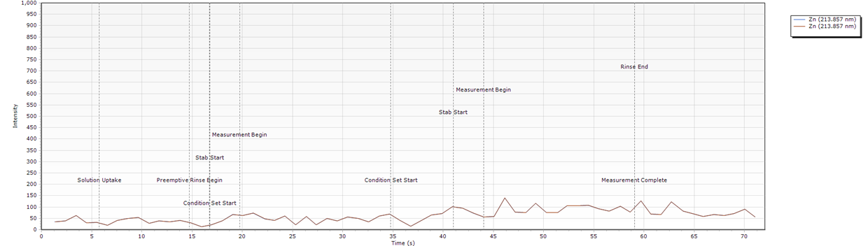
Low Unstable Signal
| Cause | Action |
| No solution in either syringe. No solution in the carrier or diluent containers. Syringe port fittings not tight. No sample is delivered. |
Fill the diluent and carrier containers and prime the syringes. See also No Signal Appears During Measurement. |
Timing Monitor examples
- The intensity is not consistent and is very low.
What condition sets were used for this example?
Base Condition Sets
Common conditions
| Common Conditions | AVS Accessory Parameter | ||
| Replicates | 3 | Pump rate - Uptake (mL/min) | 40 |
| Pump speed (rpm) | 12 | Pump rate - Inject (mL/min) | 9 |
| Rinse time (s) | 0 | Valve uptake delay | 10 |
| Fast pump | - | Bubble injection time (s) | 2 |
| Reactive dilution rinse time (s) | 0 | Preemptive rinse time | 2 |
Measurement conditions
| Measurement Conditions | |||
| Condition Set 1 | |||
| Read time (s) | 5 | Nebulizer flow (L/min) | 0.8 |
| RF power (kW) | 1.25 | Plasma flow (L/min) | 12 |
| Stabilization time (s) | 5 | Aux flow (L/min) | 1 |
| Viewing mode | Radial | Make up flow (L/min) | 0 |
| Viewing height | 8 | ||
| Condition Set 2 | |||
| Read time (s) | 5 | Nebulizer flow (L/min) | 0.6 |
| RF power (kW) | 1.35 | Plasma flow (L/min) | 12 |
| Stabilization time (s) | 3 | Aux flow (L/min) | 1 |
| Viewing mode | SVDV | Make up flow (L/min) | 0 |
| Viewing height | 9 | ||
Peak Drop Off Condition Sets
Common conditions
| Common Conditions | AVS Accessory Parameter | ||
| Replicates | 3 | Pump rate - Uptake (mL/min) | 40 |
| Pump speed (rpm) | 12 | Pump rate - Inject (mL/min) | 9 |
| Rinse time (s) | 0 | Valve uptake delay | 10 |
| Fast pump | - | Bubble injection time (s) | 2 |
| Reactive dilution rinse time (s) | 0 | Preemptive rinse time | 2 |
Measurement conditions
| Measurement Conditions | |||
| Condition Set 1 | |||
| Read time (s) | 10 | Nebulizer flow (L/min) | 0.8 |
| RF power (kW) | 1.25 | Plasma flow (L/min) | 12 |
| Stabilization time (s) | 7 | Aux flow (L/min) | 1 |
| Viewing mode | Radial | Make up flow (L/min) | 0 |
| Viewing height | 8 | ||
| Condition Set 2 | |||
| Read time (s) | 10 | Nebulizer flow (L/min) | 0.6 |
| RF power (kW) | 1.35 | Plasma flow (L/min) | 12 |
| Stabilization time (s) | 9 | Aux flow (L/min) | 1 |
| Viewing mode | SVDV | Make up flow (L/min) | 0 |
| Viewing height | 9 | ||
Delayed Peak Condition Sets
Common conditions
| Common Conditions | AVS Accessory Parameter | ||
| Replicates | 3 | Pump rate - Uptake (mL/min) | 40 |
| Pump speed (rpm) | 12 | Pump rate - Inject (mL/min) | 9 |
| Rinse time (s) | 0 | Valve uptake delay | 8.5 |
| Fast pump | - | Bubble injection time (s) | 2 |
| Reactive dilution rinse time (s) | 0 | Preemptive rinse time | 2 |
Measurement conditions
| Measurement Conditions | |||
| Condition Set 1 | |||
| Read time (s) | 5 | Nebulizer flow (L/min) | 0.8 |
| RF power (kW) | 1.25 | Plasma flow (L/min) | 12 |
| Stabilization time (s) | 5 | Aux flow (L/min) | 1 |
| Viewing mode | Radial | Make up flow (L/min) | 0 |
| Viewing height | 8 | ||
| Condition Set 2 | |||
| Read time (s) | 5 | Nebulizer flow (L/min) | 0.6 |
| RF power (kW) | 1.35 | Plasma flow (L/min) | 12 |
| Stabilization time (s) | 4 | Aux flow (L/min) | 1 |
| Viewing mode | SVDV | Make up flow (L/min) | 0 |
| Viewing height | 9 | ||
Curved Peaks at the Start of the Measurement Condition Sets
Common conditions
| Common Conditions | AVS Accessory Parameter | ||
| Replicates | 3 | Pump rate - Uptake (mL/min) | 40 |
| Pump speed (rpm) | 12 | Pump rate - Inject (mL/min) | 9 |
| Rinse time (s) | 0 | Valve uptake delay | 10 |
| Fast pump | - | Bubble injection time (s) | 2 |
| Reactive dilution rinse time (s) | 0 | Preemptive rinse time | 2 |
Measurement conditions
| Measurement Conditions | |||
| Condition Set 1 | |||
| Read time (s) | 5 | Nebulizer flow (L/min) | 0.8 |
| RF power (kW) | 1.25 | Plasma flow (L/min) | 12 |
| Stabilization time (s) | 5 | Aux flow (L/min) | 1 |
| Viewing mode | Radial | Make up flow (L/min) | 0 |
| Viewing height | 8 | ||
| Condition Set 2 | |||
| Read time (s) | 5 | Nebulizer flow (L/min) | 0.6 |
| RF power (kW) | 1.35 | Plasma flow (L/min) | 12 |
| Stabilization time (s) | 3 | Aux flow (L/min) | 1 |
| Viewing mode | SVDV | Make up flow (L/min) | 0 |
| Viewing height | 9 | ||
See also: