Setup the Sample Introduction Area
The function of the liquid sample introduction system is to deliver a uniform amount of sample to the plasma for excitation to atomic/ionic emission states. The liquid sample introduction system forms an aerosol by combining a sample together with an argon carrier gas. The aerosol is then transported to the plasma's preheating zone. As the aerosol passes through the preheated zone and into the plasma.
This page includes instructions on how to install the snout, torch, spray chamber, nebulizer, and peristaltic pump tubing. Click here for instructions on how to setup the optional AVS 4/6/7 switching valves.
Before starting your ICP-OES system, it is strongly recommended that you carefully read the Safety practices and hazards section in your ICP-OES User's Guide and ensure that the laboratory is set up according to the ICP-OES specifications as stated in the Agilent ICP-OES Site Preparation Guide.
Your ICP-OES should be ready to operate after the Agilent field service engineer has installed it.
Installing the Snout
To install the snout:
 |
Open the video and then click 'Install the Snout on the ICP-OES' in the video table of contents for instructions. |
|
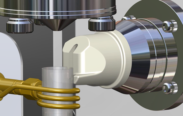
Do not hit the RF coil when installing the snout. See Figure 1. |
- Open the torch compartment door and then remove the torch.
- Remove the radial snout plug (if present).
- Slide the snout in from the right side and then gently push to fit the snout on the radial window assembly.
Figure 1. Installing the snout on the radial window assembly
- The tabs (indicated in two small red boxes on the image below) on the snout should be at the bottom and horizontal to each other.
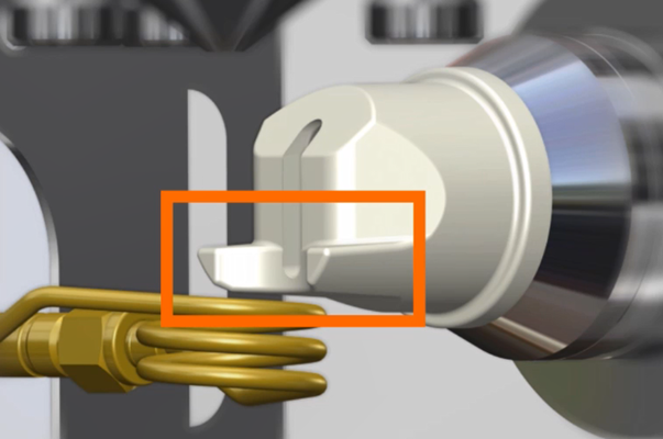
Figure 2. Tabs horizontal to each other and slot on the torch quartz tube is parallel with the slot on the snout. The RF coil is shown coiled around the torch quartz tube. - Insert the torch. The slot on the torch quartz tube should be parallel with the slot on the snout (indicated with the tall red box on the Figure above).
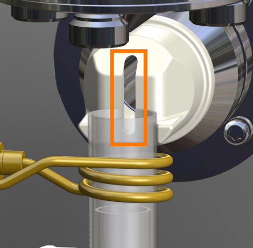
Figure 3. Slot on the torch quartz tube is parallel with the slot on the snout. The RF coil is shown coiled around the torch quartz tube.
- Gently slide the snout out toward the torch, until the end of the snout touches the wall of the torch.
- Remove the torch.
- Pull the snout off the radial assembly, slide to the right and then out of the instrument.
 |
Do not hit the RF coil when removing the snout. |
Installing and Removing the Torch
The ICP-OES torch loader is designed to be self aligning so that the torch can be installed easily.
|
Always pull the torch straight down until the torch tube has cleared the loader before pulling it away from the instrument. |
 |
This video demonstrates how to install and remove a torch. If you have a demountable torch, you may need to assemble it first. |
To install and remove the torch:
- Pull the torch loader handle towards you, so that it is in its fully open position. If there is already a torch present, ensure that the spray chamber has been detached from the torch, and then remove the torch by pulling it down out of the torch loader.
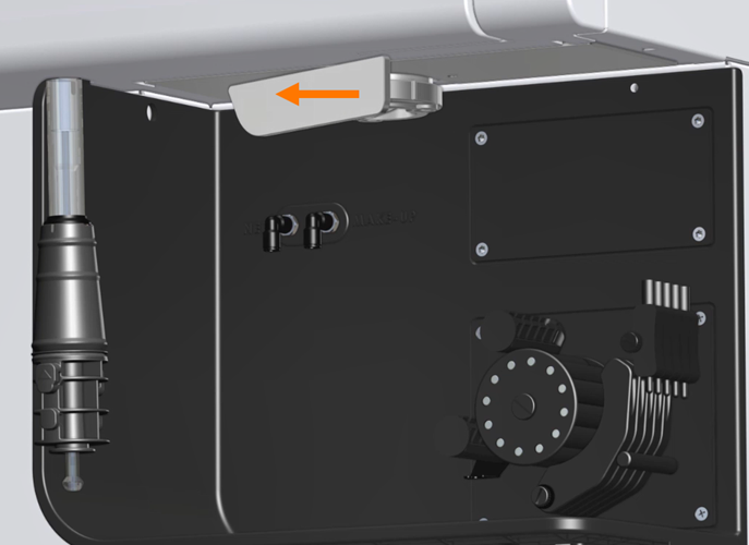
Figure 3. Opening the torch loader handle -
Holding the torch by its base and with the marker facing towards you, slide the torch up into the loader as far as it will go. Slight resistance should be felt as the base of the torch engages with the loader.
Figure 4. Torch marker |
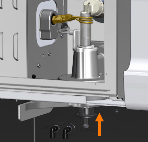
Figure 5. Inserting the torch into the torch loader |
- With the torch positioned correctly within the loader, push the torch loader handle back in towards the instrument.
- If you are using the radial view snout purge, gently slide the snout out toward the torch, until the end of the snout touches the wall of the torch.
|
Never force the quartz part of the torch up into the loader, as this may damage your instrument or cause the torch to break. |
 |
Reverse the procedure to remove the torch. |
|
Always pull the torch straight down until the torch tube has cleared the loader before pulling it away from the instrument. |
Installing the Spray Chamber
The spray chamber is where an aerosol is created from the solution that is being pumped and so its performance is of paramount importance to sample introduction.
To install the spray chamber:
 |
This video demonstrates how to install and remove a torch. If you have a demountable torch, you may need to assemble it first. |
- Attach the drain tubing to the drain port on the underside of the spray chamber.
- Position the cup of the spray chamber on to bottom of the ball fitting located on the underside of the torch. Secure the spray chamber in place using a torch clamp. It may be easier to install the nebulizer before attaching the spray chamber to the torch.
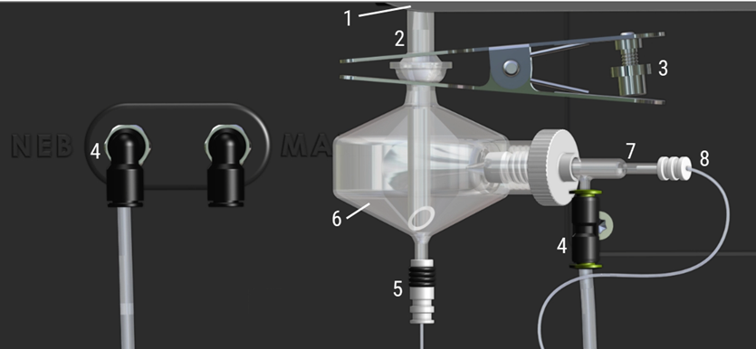
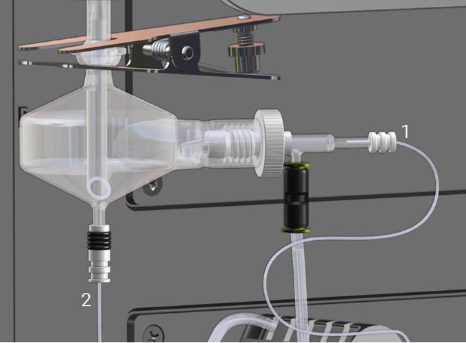
Figure 6. Torch, spray chamber and nebulizer connections
Where:
|
1. Torch loader handle |
4. Gas connection to nebulizer |
7. Nebulizer |
|
2. Torch |
5. Spray chamber drain tubing |
8. Solution delivery tubing from peristaltic pump |
|
3. Torch clamp |
6. Spray chamber |
|
The combined carrier gas and sample aerosol generated by the nebulizer are introduced into the spray chamber.
The aerosol must be injected into the plasma at a uniform rate without causing plasma destabilization. In addition to this, the aerosol that is injected into the torch must also contain a sufficient number of small droplets that are reproducible and representative of the sample. A spray chamber is used to remove the larger droplets from the aerosol while providing a uniform flow of aerosol to the torch. The spray chamber provides an interface to pass the aerosol to the torch. The design transports a fine spray to the torch, while larger droplets coalesce, fall to the bottom and are removed through the spray chamber drain by the pump and pump tubing.
Typical spray chambers used with the Agilent ICP-OES instruments include:
- Glass single-pass cyclone (Cyclonic)
- Glass double-pass cyclone (Cyclonic)
Double-pass glass cyclonic (Twister)
The Twister cyclonic spray chamber features a central transfer tube which is more efficient in removing larger aerosol droplets compared to the single-pass glass cyclonic spray chamber. This reduces solvent load in the plasma making it better suited to more difficult sample types, such as those containing higher dissolved solids (>5%) and low volatility organic solvents.
- Material: Borosilicate glass
- Volume: 50 mL
- Physical reproducibility: ~1%
- Low RSD’s - highly accurate construction. Application uptake range 0.2 to 3.0 mL/min
Installing the Nebulizer
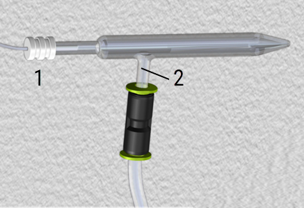
Figure 7. Nebulizer components
Where:
|
1. Solution delivery tubing fitting |
2. Nebulizer side arm (for gas connection) |
To assemble and install the nebulizer:
See the Agilent V-groove, Inert High TDS Nebulizer User's Guide for information on how to assemble and maintain the V-groove nebulizers.
 |
This video provides information on how to install the nebulizer. |
- Loosen the white knurled nut on the spray chamber (if necessary). See Figure 6.
- Insert the nebulizer into the spray chamber.
- Tighten the white knurled nut finger-tight.
- Insert the gas hose fitting onto the side arm of the nebulizer.
- Insert the gas tubing into the fitting (if necessary).
- Insert the free end of the nebulizer gas supply tubing into the gas supply port (labeled NEB) on the ICP-OES.
- Push the solution delivery tubing fitting into the nebulizer.
- Push the nebulizer into the socket on the side of the spray chamber.
- Tighten the white knurled nut finger-tight until the nebulizer is firmly held in place.
Click here for information on standard nebulizer types.Click here for information on standard nebulizer types.
Two basic types of nebulizers can be used with the Agilent ICP-OES instruments to form an aerosol.
- Pneumatic (standard)
- Ultrasonic (optional)
Glass concentric nebulizer
The glass concentric nebulizers that can be used with the Agilent instruments are:
- Seaspray - high dissolved solids nebulizer
- Conical ‘K’ type, nebulizer
SeaSpray Nebulizer
The SeaSpray nebulizer is used for trace level analyses. It has better nebulization efficiency and resists clogging with most mineral salts.
- Material: Borosilicate glass
- High physical reproducibility ~ 1% TDS tolerance, typically up to 20%
- High tolerance to particulates, typically up to 75 µm
- Low RSD's due to highly accurate construction
- Free uptake: 2 mL/min
- Gas flow: 0.7 L/min at 30 psi
Conical ‘K’ type nebulizer
The Conical ‘K’ type nebulizer is used for high precision, routine aqueous and organic applications.
- Material: Borosilicate glass
- High physical reproducibility ~ 1% TDS tolerance, typically up to 10%
- High tolerance to particulates, typically up to 75 µm. Low RSD’s due to highly accurate construction.
- Free uptake: 3 mL/min
- Gas flow: 0.7 L/min at 30 psi
PEEK nebulizers
The OneNeb and V-Groove nebulizers can be used with the ICP-OES.
OneNeb nebulizer
The OneNeb nebulizer is used for high sensitivity, organic samples, high TDS samples and HF digests.
- Material: PFA/PEEK polymer
- Precision: typically < 1% RSD
- For samples with high TDS, up to 25%
- High tolerance to particulates, up to 75 µm.
- Solution uptake range: 0.04-2.0 mL/min
V-Groove nebulizer
The v-Groove is an inert nebulizer intended for the routine analysis of challenging samples containing suspended particles and/or high total dissolved solids (TDS).
- Material: PEEK/ceramic
- Inert construction: compatible with any aqueous or organic applications, including HF
- Highest TDS tolerance: up to 30% TDS
- Highest suspended particle tolerance: up to 350 µm.
- Compatible with valve systems
- Solution uptake range: 0.2-2.5 mL/min
- Gas flow: 0.5-1.0 L min
Installing the Peristaltic Pump Tubing
The pump tubing installed on the peristaltic pump controls the flow of solution to the nebulizer. A wider internal diameter of tubing delivers more volume per pump rotation. The peristaltic pump turns in a counter clockwise direction.
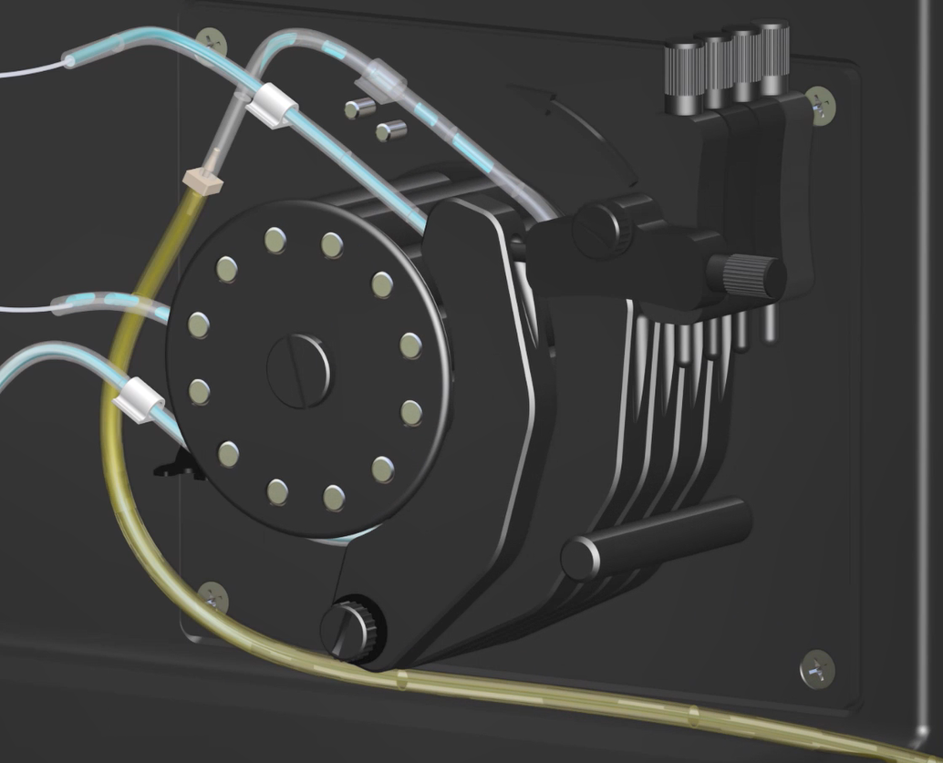 |
This video provides information on how to install and adjust the peristaltic pump tubing. |
Turning On the ICP-OES and Starting the Software
Click for instructions on how to turn on the ICP-OES and start the ICP Expert software.
See also: