About Your Inductively Coupled Plasma-Optical Emission Spectroscopy Instrument
The Agilent 5100, 5110, 5800, and 5900 Inductively Coupled Plasma-Optical Emission Spectrometer (ICP-OES) has three configurations:
- radial view, the 5100/5110 and 5800 RV ICP-OES
- dual view (radial and axial viewed sequentially), the 5100/5110 and 5800 VDV ICP-OES
- synchronous dual view (both radial and axial) , the 5100/5110 and 5900 SVDV ICP-OES, that can simultaneously analyze the full wavelength spectrum for the elemental content of solutions using emission spectroscopy.
Emission spectroscopy is a measurement technique based on the observation of the intensity of discrete wavelengths of light that atoms emit when excited at high temperatures — the wavelength of individual emission lines are associated with a particular element.
 |
This video provides information about your ICP-OES hardware. |
In addition to the video above, this page provides information about the following
Click here for information about the Sample Introduction Area.
Instrument Overview
Front of instrument
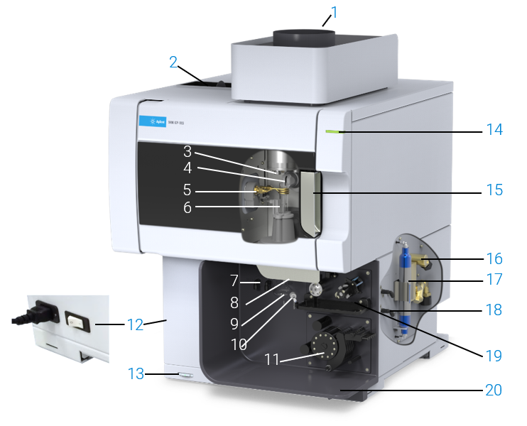
Figure 1. Agilent 5800 and 5900 ICP-OES instruments
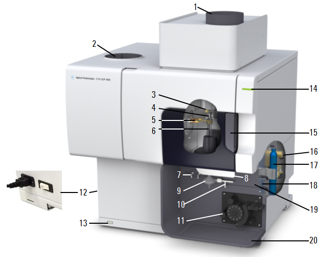
Figure 2. Agilent 5100 and 5110 ICP-OES instruments
Where:
|
Item |
Description |
|---|---|
|
1. Exhaust |
Vents out excess heat and fumes from the instrument. |
|
2. Air inlet filter |
Brings in filtered air used to help cool the instrument |
|
3. Cone and axial pre-optics viewing window (not shown) |
The cone removes the cool plasma tail where recombination of species takes place. The cooled cone interface, located in the torch compartment, protects the pre-optics window. The cone can be easily removed for cleaning. Cooling water circulates through the cooling sleeve to remove the heat. The axial pre-optic windows protect the pre-optic mirrors. |
|
4. Snout and radial pre-optics viewing window (not shown) |
The snout provides a purged optical path between the plasma and the radial pre-optics so that lines below 190 nm can be measured. The radial pre-optic windows protect the pre-optic mirrors. |
|
5. Induction coil |
The induction coil transfers energy from the RF generator to the plasma. |
|
6. Torch |
Due to its design, the torch requires no manual alignment. |
|
7. Nebulizer and make up gas connections |
The nebulizer gas provides a gas supply used to convert a solution into an aerosol and to deliver it to the spray chamber. Increase or decrease the desired flow of argon through the nebulizer, spray chamber, and torch injector tube using the ICP Expert software. The make up gas (argon) can be used with high total dissolved solids (TDS) samples to prevent build up in the torch. |
|
8. Torch loader handle |
Swing the handle to the left to open, push the handle to the right to close. |
|
9. Spray chamber |
The spray chamber's function is to act as a filter for the sample droplets. Fine droplets go through the spray chamber up to the torch and the larger droplets hit the side of the spray chamber, coalesce and move down the spray chamber drain to be removed. |
|
10. Nebulizer |
The nebulizer converts liquid sample into a fine aerosol which is sprayed into the spray chamber, where larger drops are removed and the fine drops are delivered to the torch. The nebulizer has two inlets:
The type of nebulizer selected will depend upon your instrument and the type of samples to be analyzed. |
|
11. Peristaltic pump |
The flow of liquid into the nebulizer is controlled by a peristaltic pump. The main purpose of the pump is to supply a controlled flow of liquid to the nebulizer and pump the drain liquid away from the spray chamber. Your system may include a 3 or 5-channel pump depending on the spectrometer and configuration purchased. |
|
12. Mains power switch and power cable connection |
On the left back side of the instrument. It is recommended you leave the power on unless shutting the instrument down for an extended period of time. Turning this off turns off all power to the instrument. |
|
13. Front panel power switch |
The LED in the front on/off switch indicates the basic instrument on/off state. It is recommended you leave the power on unless shutting the instrument down for an extended period of time. Turning this power button off will shut down all main systems. |
|
14. LED instrument status indicator |
The instrument status LED indicates whether the instrument is connected to the software, whether it is ready to run a plasma, or whether there is an instrument-generated error. See Instrument Status LED indicators or the ICP-OES users guide for a more detailed description. |
|
15. Torch compartment handle |
Open to gain access to the torch compartment where you can clean or replace the cone and pre-optics windows. |
|
16. Water inlet assembly |
Introduces cooling water from the chiller and filters the water to remove particulates. |
|
17. Optics purge gas filter |
Filters the argon (or nitrogen if used) gas. |
|
18. Gas supply assembly |
Up to three gas ports are available depending on the instrument model purchased: Argon, Nitrogen (optional, not shown), and Option gas (80% Ar/20% O2 mix, optional). |
|
19. Accessory location |
Location for the optional AVS 4, 6 or 7 switching valve accessory. |
|
20. Drain hole |
Drain hole for liquid overflow. |
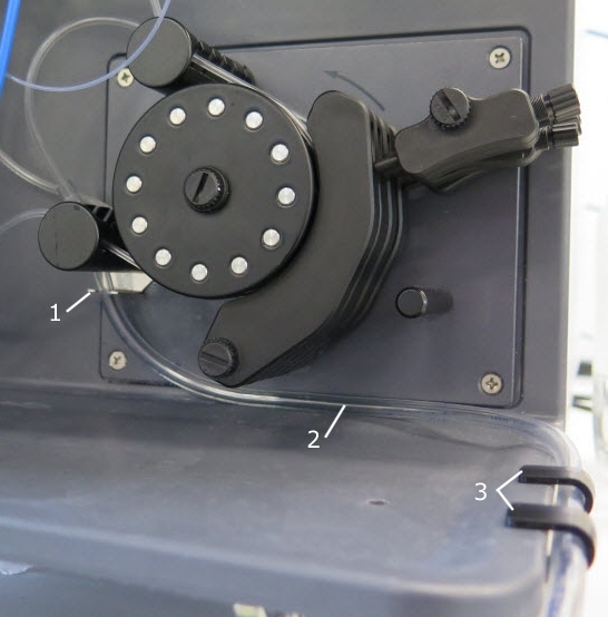
Clips for waste tubing
Use the three clips (1 and 3 in the image below) to guide the waste tubing (2 in the image below) away from the peristaltic pump and other tubing. See the image below for the tubing placement.
Right side of instrument
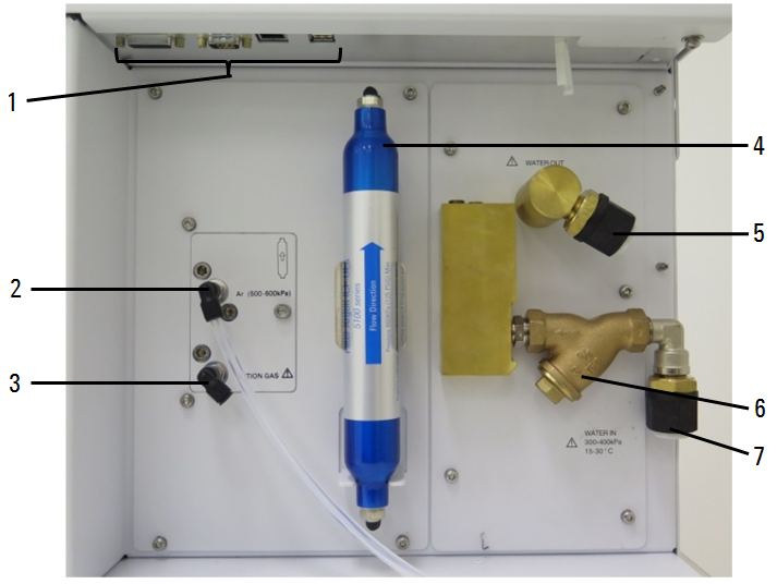
Figure 2. Input and output connections on the right side of the ICP-OES
Where:
|
|
Item |
Description |
|
1 |
Accessory and LAN cable connections |
Accessory connections and Ethernet port for PC to instrument communication For connection of Agilent-specified accessories only. See Figure 3 below. |
|
2 |
Argon gas inlet |
Argon gas inlet, standard |
|
3 |
Option gas inlet |
Option gas (80% Ar/20% O2 mix, optional) Nitrogen gas inlet, optional (not shown) |
|
4 |
Optics purge gas filter |
Argon or nitrogen (if used) gas filter |
|
5 |
Water outlet |
Connect to water chiller |
|
6 |
Water filter |
Coarse particulate water filter |
|
7 |
Water inlet |
Connect to water chiller |
Communications ports
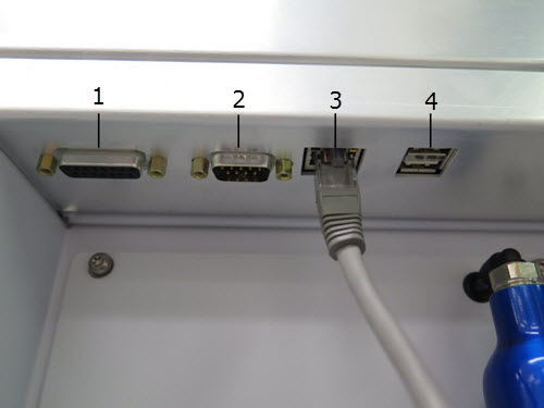
Figure 3. Input and output connections on the side of the ICP-OES
Where:
|
|
Item |
Description |
|
1 |
Accessory port |
DA-15 receptacle For connection of Agilent-specified accessories only |
|
2 |
Autosampler port |
DE-9 plug. RS-232 port for connection of an autosampler |
|
3 |
Ethernet |
Communication cable to the PC |
|
4 |
USB port |
USB type B receptacle. Supports USB 2.0 Full Speed For connection of Agilent-specified accessories only |
Interlocks and Internal Monitoring
The spectrometer incorporates interlocks and covers that are used to monitor critical operations to ensure instrument protection. If the instrument is used in any manner not specified by Agilent, this protection may be impaired. It is good practice to develop safe working habits that do not depend upon the correct operation of the interlocks for safe operation. It is essential that no interlock or cover is bypassed, damaged or removed.
A brief description is provided for these available interlock types.
Torch Compartment Door Interlock
The torch compartment door interlock monitors the state of the internal interlock. An open interlock switch will inhibit plasma ignition or extinguish an existing plasma.
Torch Loader Interlock
The torch loader interlock monitors the state of the internal interlock on the torch loader handle. An open interlock switch will inhibit plasma ignition or extinguish an existing plasma.
Instrument Temperature, Gas Flow and Pressure Monitoring
The ICP-OES monitors a number of internal temperatures, gas flows and pressures. If they fall below or exceed specified limits the instrument will inhibit plasma ignition or extinguish an existing plasma.
Water Flow Monitoring
A water flow switch is fitted on the water manifold assembly. If there is insufficient water flow an error message 'Low water flow' is displayed in the ICP Expert software, and plasma ignition is inhibited. If this error is detected while the plasma is in operation, an immediate shutdown will occur.
Cooling Fan Monitoring
Cooling fan operation is detected by an air flow sensor. If the air cooling flow is detected to be insufficient, the instrument will inhibit plasma ignition or extinguish an existing plasma.
Plasma On Monitoring
An optical detector in the ICP-OES is positioned to detect light emitted by the plasma. If the plasma goes out an alert message is displayed in the ICP Expert software. If this fault condition is detected while the plasma is on, the RF generator and the gas control unit are shut down.
RF Control Watchdog
The RF control watchdog effectively controls the plasma generating system. If the watchdog system detects that the plasma generation system is not operating correctly, the high voltage supply is shut down.
High Voltage Power Supply Failure
If an overload condition is detected, ignition of the plasma will be inhibited or, if the plasma is already running, the RF power is shut down and the plasma is extinguished.
See also: