ADS 2 Installation
 |
You must do the following before installing the ADS 2:
|
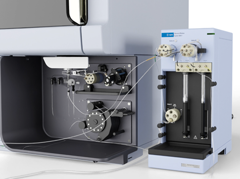
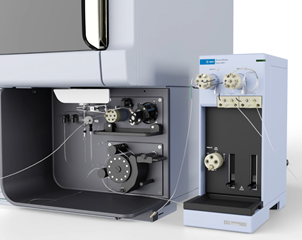
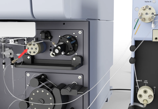
Placement of the ADS 2 next to the ICP-OES
The following steps are performed during the installation of the ADS 2 hardware:
- Ensure all required cables, components and tubing are available.
- Connect the communication and power cable.
- Install the tube clips.
- Install the dilution loop holder.
- Install the drain tube.
- Connect the Valve A to Valve C tubing.
- Install the syringes.
- Install the autosampler to ADS 2 and AVS tubing.
- Install the AVS pump tubing.
- Turn on the ADS 2 and initialize and prime.
- Run the Advanced Dilution System 2 performance test.
 |
Perform the instructions demonstrated in this video to install the ADS 2 onto an ICP-OES. Instructions are also provided below. |
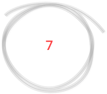
Ensure all Tubing and Components are Available
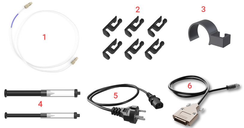
Where:
| 1. ICP-OES to AVS Pump tubing with purple label, 2 pieces | 2. Tube clips, 6 pieces | 3. Dilution loop holder |
| 4. 10 mL diluent and 5 mL carrier solution glass syringes | 5. Power cable | 6. Communications cable |
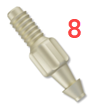
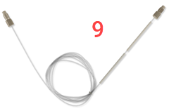
| 7. Waste tubing | 8. Waste barb (may be preinstalled on Valve C) | 9. 1.0 mL dilution loop |
Connect the Communication and Power Cable
- Push the communications into the port on the back of the ADS 2.
- Finger-tighten the silver colored end until the cable is secure.
Connect the communication and power cables onto the back of the ADS 2
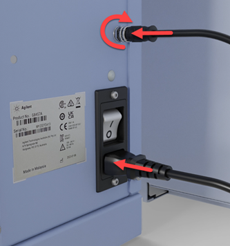
- Push the power cable firmly into the port on the back of the ADS 2.
- Connect the power cable to the mains power.
- Remove the side panel from the ICP-OES Utilities Compartment.
- Insert the connector and then tighten the two screws to secure the communication cable into the port labeled Agilent Accessory Only.
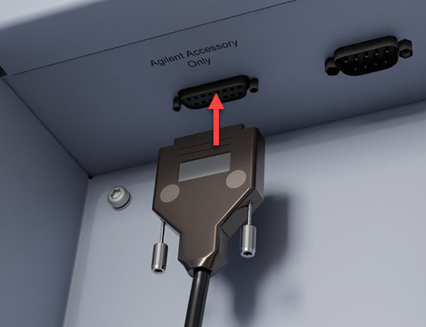
Connect the communication cable in the utilities compartment
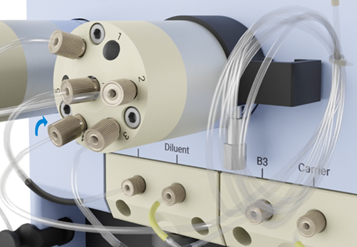
Install the Tube Clips
Plug are present in ports 1 and 7 (not shown).
A barrier plug is installed in Port 2 (not shown) for use in bubble injection.
Supplied plugs will look different to those shown in this video.
- Install the 6 tubing clips in the location and direction shown in the image below. The open side of the clip should point the same direction as the arrows.
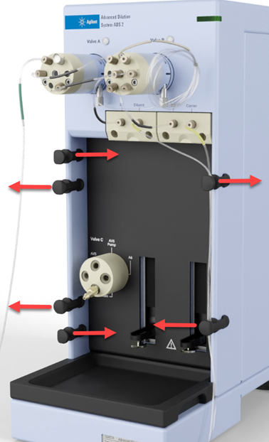
- Thread the two pieces of tubing with the yellow labels through the 2 tube clips on the right side of the ADS 2.
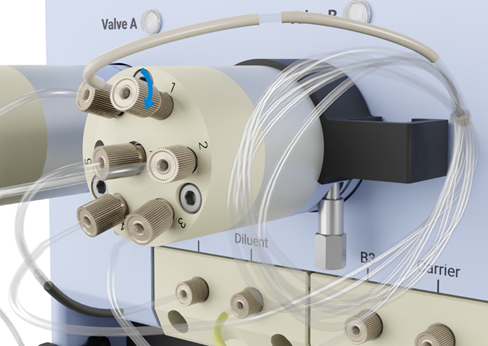
Install the Dilution Loop Holder
Install the dilution loop holder in the direction shown in the image below.
- Push the dilution loop holder onto Valve B.
- Slide the preinstalled dilution loop inside the hook on the dilution loop.
- Push the dilution loop until it is flush with the ADS 2 body.
Replace the Dilution Loop Tubing
See item 9 on the above image. The ADS 2 comes standard with a 1.5 mL dilution loop installed. For the ADS 2 performance test, you must install the 1.0 mL dilution loop provided with your ADS 2. You can replace it with the desired dilution loop after the performance test has passed.
The AVS sample loop and ADS 2 dilution loop must be the same size.
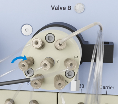
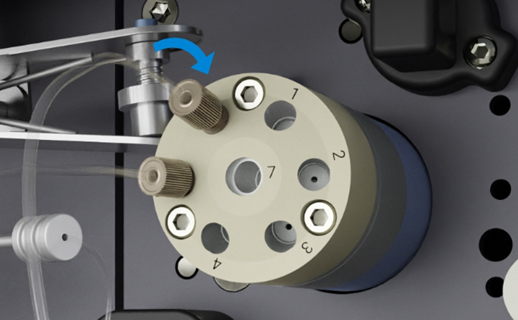
- Disconnect the fitting on the 1.5 mL dilution loop in port 1 on Valve B on the ADS 2.
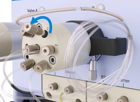
- Disconnect the fitting port 4 on Valve B. Store the loop in a safe place.
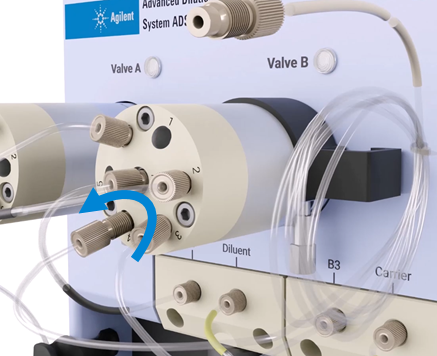
- Insert, and finger-tighten, the fitting on the 1.0 mL dilution loop tubing into the port 4 on Valve B on the ADS 2.
- Insert, and finger-tighten, the fitting on the free end of 1.0mL dilution loop tubing into the port 1 on Valve B on the ADS 2.
- Route the tubing through the dilution loop holder and then push the holder until it sits flush with the ADS 2 body.
Install the Drain Tube
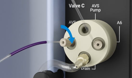
- If the Waste barb on Valve C isn't installed, remove it from the packaging and screw it into the Port labeled Drain on Valve C.
- Remove the train tubing from the packaging and then slide one end onto, and then just beyond the tip of the barb.
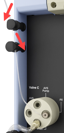
- Route the tubing through the tube clips as shown in the image below.
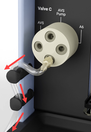
- Place the other end of the tubing into the waste container. See the waste container instructions if cap assembly is required.
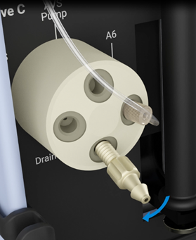
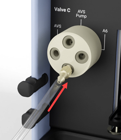
Connect the Valve A to Valve C Tubing
Tubing with a green label comes preinstalled on Valve A, Port 6. The other end is not connected.
- Connect, finger-tight only, the free end of the tubing with the green label into the port labeled A6 on Valve C.
- Route the tubing through the tube clips as shown in the image below.
Install the Syringes
Two syringes are required: 10 mL for the diluent and 5 mL for the carrier solutions. Standard syringes provided have glass barrels. The syringe is disassembled for transport. You will need to assemble the syringe and then place it onto the ADS 2.
|
For quartz syringe barrels only: If you are using the quartz diluent syringe instead of the standard glass syringe, take note of the syringe volume calibration value on the syringe barrel. You will need it later in this procedure. |
Assembling the Syringe
- Remove both the plunger and barrel from the packaging.
- Dip the tip of the plunger into distilled water and then slowly insert the plunger into the barrel.
- Stroke the syringe 10 times while applying steady and even pressure. Avoid twisting movements.
 |
Broken glass Danger to hands. Always wear protective equipment when handling glass or quartz to prevent breakage and cuts. Do not use if chipped or cracked. |
- Repeat Steps 1-3 for the second syringe.
Installing the Syringe
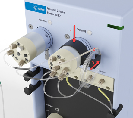
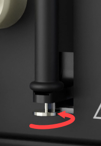
- Insert the threaded end of the diluent syringe barrel into the ADS 2. Screw in the syringe finger-tight only.
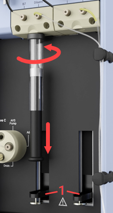
- Gently pull down on the plunger until it meets the syringe driver (1 in the image above).
- On the syringe driver, ensure the silver knurled screw meets the threaded hole in the bottom of the plunger.
- Finger-tighten the silver knurled screw until it fully secures the plunger to the syringe driver.
- Repeat for the carrier solution syringe.
Install the Autosampler to ADS 2 and AVS Tubing
There are 2 pieces of tubing that will need to be moved:
- Removing the autosampler probe tubing from the AVS valve and connecting it to the ADS 2.
- Connecting the autosampler tubing from the ADS 2 to the AVS.
- Disconnect the autosampler probe tubing connected to Port 5 on the AVS valve.
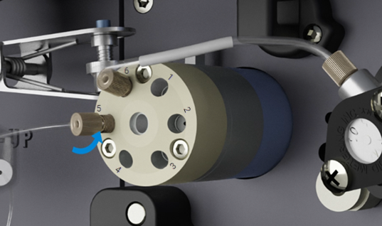
- Connect the free end of the autosampler probe tubing, finger-tight only, into Port 5 on Valve B on the ADS 2.
- Connect the free end, finger-tight only, of the pre-installed tubing with the orange label from Port 4 of Valve A on the ADS 2 into Port 5 on the AVS.
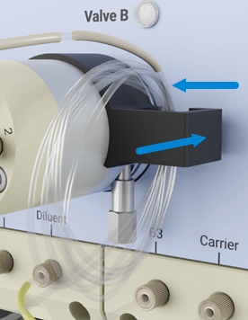
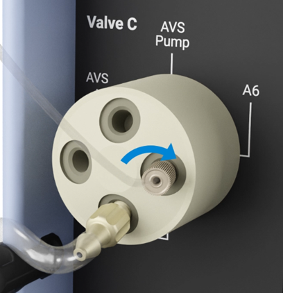
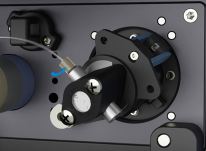
Install the AVS Pump Tubing
This procedure requires removing the tubing from the AVS valve Port 6 to the inlet of the AVS pump. Keep this tubing for troubleshooting purposes or if the ADS 2 is moved from one ICP-OES to another.
For clarity, this procedure shows the AVS valve without the additional tubing installed. All of the AVS tubing should already be installed.
- Disconnect the tubing from the AVS valve port 6 to the inlet of the AVS pump.
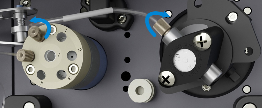
- On the ADS 2, connect one end of the tubing with the purple label, finger-tight only, into the port labeled AVS on Valve C.
- Connect the free end of the tubing from the port labeled AVS on Valve C to port 6 on the AVS switching valve.
- On the ADS 2, connect one end of the tubing with the purple label, finger-tight only, into the port labeled AVS Pump on Valve C.
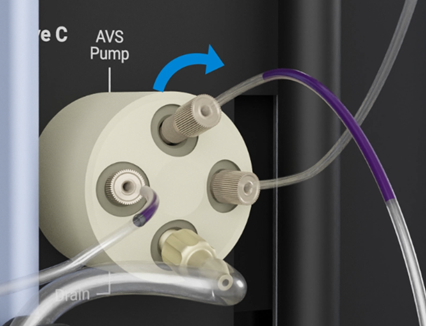
- Connect the free end, finger-tight only, to the in inlet end of the AVS pump.
Turn On the ADS 2
Before turning on the ADS 2
- Ensure the torch, nebulizer, spray chamber, and pump tubing are clean, in good working condition, and installed on ICP-OES
- Use a 1.4 mm injector for Radial views or a 1.8 mm injector for Dual view
- The external instrument exhaust and instrument are turned on
- The ICP-OES instrument is turned on
- Wavelength calibration solution must be available
- A 1% nitric acid (analytical reagent grade) Blank and Rinse solution should be prepared using de-ionized water
- Ensure the instrument is powered on, with the cooling water connected and flowing, and the boost gas purge enabled for at least 2 hours before performing the test
- Plasma should be on for at least 10 minutes before testing
- The instrument calibration (wavelength calibration) and the detector calibration (dark current scan) must be valid
Turn on the ADS 2, Initialize and Prime
If you are using the quartz diluent syringe, enter the syringe volume calibration value into ICP Expert before running the ADS 2 Performance Test. You will also need to select the dilution loop size installed on the ADS 2. Once all selections have been made, you must then Initialize and then Prime the ADS 2.
- Turn on the ADS 2. The power switch is on the back of the ADS 2.
- Fill the carrier, rinse, and diluent containers and place in position.
- Place the end of the waste tubing into the waste container, the end of the carrier and diluent tubing into their containers.
- Open the ICP Expert software and create a new Quantitative worksheet.
- On the Configuration tab in the worksheet, select Autosampler and then ADS 2 from the Accessory drop-down menu.
- Click Instrument in the ICP Expert toolbar.
- Click Configuration.
- In the ADS 2 Configuration section, if you are using the quartz 10 mL syringe, enter the syringe volume calibration value in the Diluent syringe volume field.
- Select the 1.0 mL Loop volume for the dilution loop installed on the ADS 2. The 1.0 mL loop was installed during the installation procedure.
The dilution loop on the ADS 2 and the sample loop on the AVS MUST be the same size loop. You can change the loops to the desired size after performing the Advanced Dilution System 2 performance test. - On the Instrument window, click the drop-down ADS 2 menu and then choose Initialize.
This will fill the syringes, switch the valves and begin priming the lines. - Once Initialize has finished, choose Prime from the ADS 2 drop-down menu.
Run the Advanced Dilution System 2 Performance Test
Click here for instructions on how to run the Advanced Dilution System 2 Test.