ADS 2 Maintenance
ADS 2 Maintenance Checklist
The following parts of the ADS 2 require routine maintenance. Any maintenance procedures not specifically mentioned should be carried out only by Agilent-trained, Agilent-qualified or Agilent-authorized field service engineers.
Daily
- Clean the surface of your ADS 2 (spills should be cleaned up immediately).
- Inspect all valve ports and fittings for leaks. Re-tighten fittings or replace tubing if necessary. Any residual fluid at the connection points should be rinsed with de-ionized water (DIW) immediately.
- Check for blockages in the tubing, sample probe or connectors. Replace tubing if blocked.
- Check that the dilution loop on Valve B is filling completely for the first few samples in the first run of the day. Failure to fill the loop completely usually indicates the rotor seal may need to be cleaned or replaced.
- Check for increases in carryover in blanks. If carryover is increasing, the valve may require the rotor seal and/or stator to be cleaned or replaced.
- Verify that a rinse with clean solvent (rinse solution or DIW) has been programmed (for 5-10 minutes) at the end of the sequence. Rinsing with clean solvent will help to flush out any remaining acids and sample matrix from the solution flow path prior to shut-down.
Weekly
- Clean the rotor seal, stator and hex screws in Valves A and B.
- Run the Advanced Dilution System 2 Test
Removing and Replacing the ADS 2 Switching Valves A and B
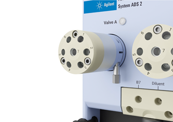 |
This video demonstrates how to remove and replace the AVS stator, rotor and valve assembly. |
  |
Chemical Hazard |
To remove the valve assembly:
- Disconnect all tubing and fittings from the switching valve.
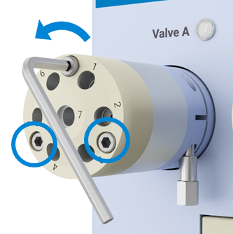
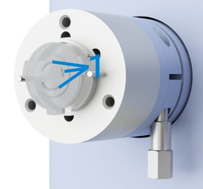
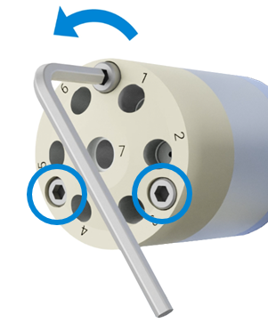
- Use the supplied 1/16 inch socket wrench to loosen the valve securing nut (1 in the image below).
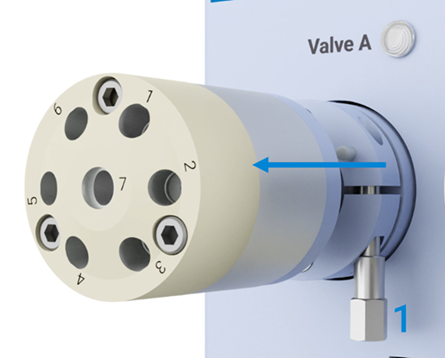
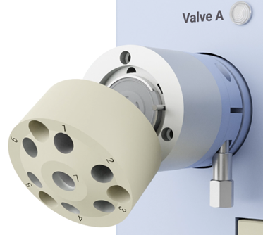
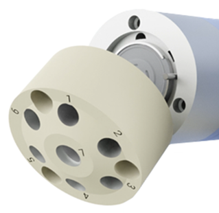
- Gently pull the valve straight out of the instrument.
To install the valve assembly:
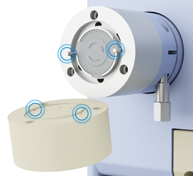
- To install the new valve assembly, match the hole labeled 'K' to the peg on the valve base. Both are indicated by the blue circles on the following image.
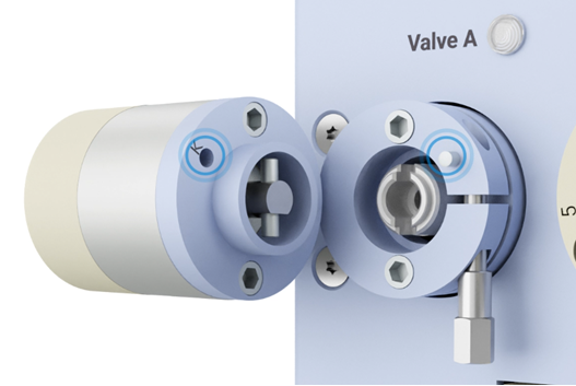
- Gently slide the valve onto the ICP-OES.
 |
The valve and pin are designed so that the valve will only insert in the correct orientation. Do not force the valve. |
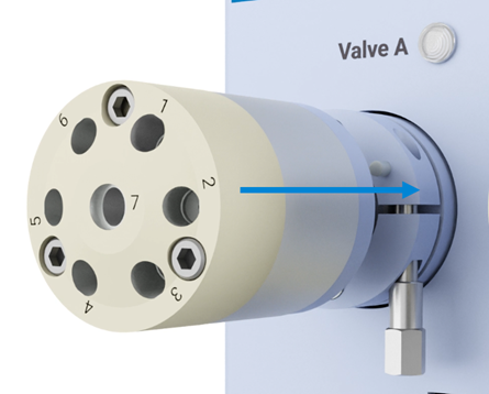
- Using the supplied wrench, tighten the valve securing nut by approximately 1/4 turn.
- Connect the tubing and fittings to the switching valve.
|
After replacing all required components, perform the Advanced Dilution System 2 test on the Instrument > Tests window. |
Replacing the Stator and Rotor
|
This video demonstrates how to remove and replace the AVS stator, rotor and valve assembly. |
Over time the stator and rotor can become worn or damaged by chemicals. To access the rotor, the stator and body ring must be removed first.
| |
Chemical Hazard |
|
If the stator has been damaged or needs replacing, always check the rotor condition and clean or replace as needed. |
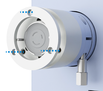
- Remove the three screws that secure the stator to the valve body using the 7/16 inch hex key provided with the valve.
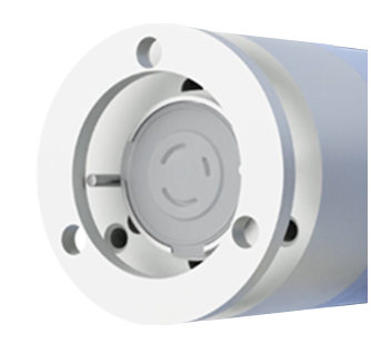
- Remove the stator from the switching valve body.
- Remove the stator.
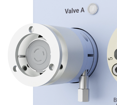
- Remove the body ring off the valve body.
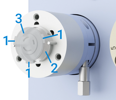
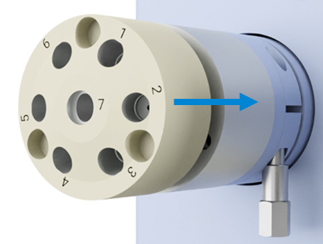
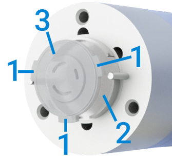
- Pull the rotor (3 in the image below) out of the driver (2) by the tabs (1).
- Wipe the driver and valve body with a soft cloth and deionized water to clean, if required.
- Clean or replace the rotor.
- Thoroughly dry before replacing the rotor and valve body.
To replace the rotor and stator:
- Insert the rotor with the liquid channel side facing out.
|
The cutouts on the driver and tabs on the rotor align so that the rotor can only go in one way. |
- Place the body ring on the valve body. Ensure that the body ring holes are aligned to the screw holes in the valve body.
- Place the stator so that the holes in the back match the alignment pins on the valve body. The screw holes should line up with the ones in the body ring and valve body.
- Insert and tighten each screw evenly in turn to ensure consistent pressure. Check that there are no gaps between the stator, the body ring, or the valve body.
- Replace the tubing and fittings onto the valve.
|
After replacing all required components, perform the Advanced Dilution System 2 test on the Instrument > Tests window. |
Cleaning the Rotor Seal, Stator and Hex Screws
| |
Chemical Hazard |
- Remove all tubing from the valve head.
- Remove the switching valve from the instrument.
- Use the supplied 1/16 inch socket wrench to loosen the valve securing nut (1 in the image below).
- Gently pull the valve straight out of the instrument.
- Remove the three screws that secure the stator to the valve body using the 7/16 inch hex key provided with the valve.
- Remove the stator from the switching valve body.
- Remove the body ring off the valve body.
- Pull the rotor (3 in the image below) out of the driver (2) by the tabs (1).
- Rinse all switching valve components with deionized water. Replace the components if damaged.
- Reassemble the valve.
Cleaning the ADS 2 syringes
| |
Chemical Hazard |
- In ICP Expert, on the top toolbar, click ADS 2 > Change Syringe.
- Follow the prompts and then click OK when the syringes have been purged.
 |
Always wear protective equipment when handling glass or quartz to prevent breakage and cuts. Do not use if chipped or cracked. |
- Remove the plunger from the syringe barrel.
- Rinse the plunger and inside the syringe barrel with a cleaning solution such as ultrapure water, dilute acid or alkaline laboratory detergent.
- Ultrasonicate the plunger, if required, in cleaning solution.
|
Do not immerse the entire syringe barrel in cleaning solution or solvent. Glued parts can become dislodged. |
- Rinse the plunger and inside the syringe barrel well with ultrapure water.
- Slowly insert the plunger into the barrel.
- Stroke the syringe 10 times while applying steady and even pressure. Avoid twisting movements.
- Follow the ‘Install the syringes’ procedure.
See also: