SPS 4 and SPS 6 Autosamplers
The SPS 4 and SPS 6 autosamplers have state-of-the-art autosampler design. The autosamplers are random access, single probe autosamplers for the front-end automation of several of Agilent's instruments.
To connect the autosampler to the ICP-OES:
- Remove the panel on the right side of the ICP-OES by holding the panel at the rear and pulling it to the right, freeing it from the retaining clips at the rear.
- There are two ways to connect the USB communications cable:
- Connect the USB cable from the autosampler into the USB port on the ICP-OES (4 in the figure below) OR
- Connect the USB cable to the PC instead of the ICP-OES instrument. If you connect the USB cable directly to the PC from the autosampler you must select 'Connect to PC Port' and choose the COM port on the File > Options > General page. Use the procedure below to determine the COM port.
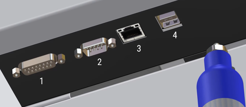
Figure 1. Input and output connections on the side of the ICP-OES
Where:
|
|
Item |
Description |
|
1 |
Accessory port |
DA-15 receptacle For connection of Agilent-specified accessories only |
|
2 |
Serial port |
DE-9 plug. RS-232 port for connection of Agilent-specified accessories |
|
3 |
Ethernet |
Communication cable to the PC |
|
4 |
USB port |
USB type B receptacle. Supports USB 2.0 Full Speed USB connection from the autosampler |
- Connect the tubing from the autosampler to the solution inlet line on the peristaltic pump.
- Select the autosampler and the settings on the Options > General page.
For detailed installation information specific to the autosampler, see the documentation supplied with your accessory.
 |
Tip |
Determining the autosampler COM Port
The software will try to determine the correct port when the "Connect to PC Port" option is enabled. If the sampler is connected it typically finds the correct port and selects it by default. If it is not able to find the correct port, follow the procedure below.
- Right-click Start and then select Device Manager.
- Expand ‘Ports’.
- Find the ‘SPS4 USB Interface’* and note the assigned COM port (COM5 in the example shown below).
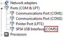
*The SPS 6 will also use the SPS4 USB Interface entry
 |
If the autosampler is connected to the PC instead of the instrument, and you are using a different autosampler to the one originally configured, the COM port will change. You must determine the new COM port using this procedure and then select that new COM port value on the Options > General page. |
Calibration Wizard
The sample probe may be displaced from the center due to the sample probe hitting a sample vial or the sides of the fixed wash reservoir. User calibration allows for minor adjustments to center the sample probe on an autosampler that is misaligned. The calibration wizard enables manual re-alignment of the sample probe using four calibration points where all corners in the movement range of the probe arm are used. At each calibration point, adjust the probe position.
|
The autosampler must be connected directly to the PC, not the ICP-OES instrument, for the Calibration Wizard to work correctly. If it is connected to the ICP-OES, before attempting to use the Calibration Wizard, remove the autosampler communications USB cable from the ICP-OES and plug it into the PC. Determine the COM port by following the instructions Determining the autosampler COM Port. |
Before starting this procedure, always check the following:
- The probe is straight and mounted tightly to the Z-axis slide.
- The spill tray and rack location mat are fitted correctly.
- Sample tubes sit vertically in the sample rack and are not leaning to one side. If the sample tubes are not suitable for use with the sample rack, change them to the correct diameter tubes to suit the sample rack or change to the correct sample rack size.
- The fixed wash reservoir is correctly mounted.
- The rack configuration is correct.
- The probe should pass through the center of the accessories plate (if present) at the bottom of the probe arm.
- Reset the unit and attempt to enter the fixed wash reservoir again.
If you are unsure of any of the above, check the Agilent SPS 4 and SPS 6 Autosampler User's Guide for detailed instructions. If checking or performing the above does not fix the issue, perform a calibration using the Calibration Wizard.
|
Close the ICP Expert application software before launching the Calibration Wizard. |
To access the Calibration Wizard:
- Click Start > All Apps> Agilent > ICP Expert > SPS 4 Calibration Wizard*.
*The SPS 6 will also use the SPS4 Calibration Wizard
To edit the rack configuration in the Calibration Wizard:
- Ensure the SPS 4 Calibration Wizard is closed.
- In ICP Expert, click Autosampler on the ICP Expert toolbar.
- Edit the racks to the desired configuration.
- Choose a position on a rack and then double-click to move and lower the probe to that position.
- Repeat Step 4 for each rack on the autosampler.
- Close ICP Expert and then open the SPS 4 Calibration Wizard.
About the Calibration Wizard Window
The following describes the calibration wizard window.
- Com Port: This area is used to connect this wizard to your autosampler. When the wizard starts, select the relevant COM port, and then click Connect.
- Undo button: Reverts to the original calibration values and restarts the calibration process.
- Reset button: Starts the calibration process.
- Z Axis Position: This area is used to adjust the Z-axis position of the sample probe at each calibration point. The indicator shows the present height of the sample probe. The Up/Down bottoms move the sample probe height.
- Probe Arm: This area is used to adjust the X and Y-axes positions of the sample probe at each calibration point.
- “Rear Left”, “Rear Right”, “Front Left”, and “Front Right” buttons: Moves the probe to the selected calibration point. Since the general calibration process automatically moves the probe in the correct order, you do not need to use these buttons. If you want to try again after performing a general calibration, we recommend moving the probe to the calibration point you want to recalibrate.
The indicators next to the calibration point buttons indicate the following status:
- Orange: Ready to calibrate at this point.
- Green: Calibration successful at this point.
- Red: Not ready or calibration error.
- Arrow buttons: Adjusts the XY position. Use the single arrow buttons to move the sample probe 0.1 mm for fine adjustments and the double arrow buttons to move it 1 mm for larger adjustments.
- Capture button: Stores the calibration data at each calibration point. Press this when the probe is centered in a good position in the sample well.
Performing a Calibration
To perform a user calibration:
- Ensure the autosampler power is on.
The sample racks fitted should be empty and not contain any sample vials. If a microtiter plate adapter is fitted, it should be loaded with four 96 well microtiter plates.
- Start the Calibration Wizard software.
- Select the appropriate COM port from the drop-down list, and then click Connect in the Com Port field.
- If the calibration wizard can connect to your autosampler successfully, the Mat Layout field shows the information on the rack layout specific to your autosampler. Ensure that the sample rack types displayed on the screen correspond to those loaded into their respective positions on the rack location mat.
If you chose the wrong one, an error message appears. If the appropriate COM port number is not listed, check the autosampler power, the USB connection, and the COM port setting in the instrument control software.
- Click Reset to start the calibration process.
|
During the calibration process, it is important that you do not click the Capture button while moving to the different calibration points. If you have adjusted the position to be too far away from the theoretical XY position at any point during the calibration, an error message is displayed to instruct you to try again. |
- The button labeled “Rear Left” changes to orange and the sample probe moves to point “Rear Left” above the far left sample well in the sample rack or microtiter plate in that position. The sample probe is at the top of the Z-Axis stroke (i.e., the Z- axis position is zero).
- To adjust the probe position in point “Rear Left”:
- Adjust the sample probe height to the top of the sample well using the Up/Down buttons.
- Adjust the XY position to the middle of the well using the arrow buttons.
- When the position of the probe is centered in the sample well, click Capture.
The indicator next to the “Rear Left” button changes from orange to green.
- When point “Rear Left” is captured, the sample probe moves to point “Rear Right” above the far right sample well in the sample rack or microtiter plate in that position, and the indicator next to the button labeled “Rear Right” changes to orange.
- Repeat Step 7 a,b, and c for the remaining three positions in the following order: "Rear Right", "Front Left", and then "Front Right".
After each position has been completed, the autosampler will automatically move to the next position.
- When all four points have been captured, a confirmation message is displayed asking if you want to write the new calibration values.
- Click Yes to write the calibration values. The autosampler is adjusted using the new calibration value.
- Click No if you want to retry. The calibration process is restarted.
- After calibration has been successfully completed, check the positioning of the sample probe by clicking on each corner position button, and driving the Z-Axis position down. Confirm that the sample probe is positioned in the center of each well.
Calibration Wizard Troubleshooting Error List
On running the calibration wizard software, you may encounter any error listed below:
Serial Port Error
Example: Autosampler did not respond.
A serial port error occurs if the software cannot communicate with the autosampler. Check that the power is on, and no error lights are illuminated. Also confirm the USB connection and the COM port setting in the instrument control software. If the problem still remains unresolved, contact your Agilent customer support representative.
Envelope Error
Example: Probe reached the maximum Y limit.
An envelope error occurs if you try to move the sample probe outside its motion envelope limits. If the well position is outside the motion envelope, contact your Agilent customer support representative.
Capture Failure
Example: Probe is too far from starting point.
A capture failure occurs if the point you are trying to capture is too far away from the expected position. Check that the sample probe positions above the correct well position, and the sample racks you are using match the description in the Calibration Wizard. If the problem still remains unresolved, contact your Agilent customer support representative.
Autosampler Error
Example: Move Z failed with ERR(8).
An autosampler error occurs if the arm has a collision, such as if the probe hits the sample rack. If this happens, click the Reset button. The autosampler will reset, and the calibration process can be continued. If the problem still remains unresolved, contact your Agilent customer support representative.
Skipping Calibration
Example: None of the positions were adjusted. Skipping calibration.
If all four captured positions are within 0.5 mm of their original position, the existing calibration is deemed to be accurate, so the calibration does not be adjusted. In this case, any problems you are having are unlikely to be caused by alignment. Contact your Agilent customer support representative.
|
For autosamplers other than the Agilent SPS 3, SPS 4 and SPS 6, it is not always possible for ICP Expert to detect when the autosampler has gone out of alignment. Therefore, it is not always possible for a run to be stopped in this situation. |
See also: