How to Create a Custom Rack
Use the Custom Rack Editor to create new autosampler rack configurations.
Click  in the Tools field on the Autosampler page to open the Custom Rack Editor window.
About custom racks
- Custom rack definitions (the .txt file that contains all of the rack settings) are also saved to a default folder in My Documents> Agilent > ICP Expert > Autosampler and can be copied to other computers with ICP Expert. The racks are then available to be used in new worksheets.
- The numbers on the tubes in the custom racks window represent the order in which the solutions in the tubes will be measured.
- Accessing the custom rack editor from the toolbar does not save the custom rack in a worksheet.
- Accessing the custom rack editor from the worksheet Autosampler page will save the new rack information with the worksheet once the worksheet is saved.
Creating a custom rack
To create a custom rack:
- Obtain the specifications of the rack you wish to use.
- Carefully measure any missing specifications. See Custom rack editor fields for measurement examples.
- Enter the required information into the custom rack editor fields mentioned below.
- Test the positioning of the probe over multiple points on the rack to ensure the probe stops in the center of the tubes.
- Determine the optimum probe depth.
Custom rack editor fields
Click in the Tools field on the Autosampler page to open the Custom Rack Editor window.
The File menu includes the following:
- Load - load previously created custom rack definitions
- Save as - save newly created custom rack definitions. The default location is C:\Users\User\Documents\Agilent\ICP Expert\Autosamplers.
- Copy to clipboard - copies the rack definition information which can then be pasted into applications such as Microsoft Notepad, Word, or Excel.
The main fields are:
- Rack label - the visible, selectable rack name found on the Autosampler page.
- Width (mm) - width of the custom rack
- Length (mm) - length of the custom rack
- Number of columns - the number columns on the custom rack
- Number of rows - the number of rows on the custom rack
- Tube diameter (mm) - the diameter of the tube used in the custom rack
- Tube volume (mL) - the volume of the tube used in the custom rack
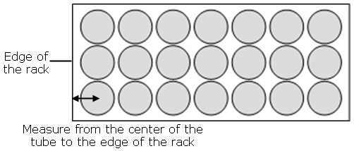
- Tube row offset (mm) - the positioning of the left column of tubes relative to the left side of the rack in the diagram. A value of '0' represents the left edge of the rack passing through the center of the tubes in the left column
For example:
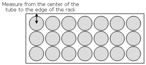
- Tube column offset (mm) - the positioning of the top row of tubes relative to the upper side of the rack in the diagram. A value of '0' represents the top edge of the rack passing through the center of the tubes in the top row
For example:
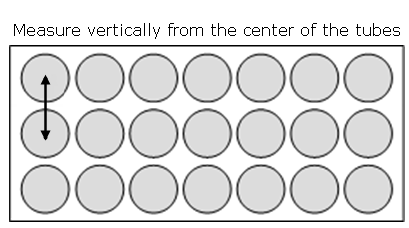
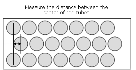
- Tube row separation (mm) - the distance between the center line of each column of tubes
For example:
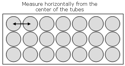
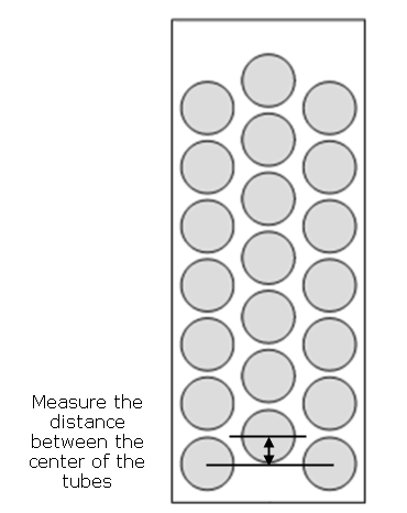
- Tube column separation (mm) - the distance between the center line of each row of tubes
For example:
- Alternate row offset (mm) - the change in the positioning of tubes in row 1, and every second row after that, along the X-axis of the rack
For example:
- Alternate column offset (mm) - the change in the positioning of tubes in column 1, and every second column after that, along the Y-axis of the rack
For example:
- Row/Column order - changing the selection between these two buttons will alter whether tube numbers are displayed (and used by the autosampler) across columns or rows of the rack
Testing and adjusting the probe position
To test the probe position:
- Right-click the rack position and then select the correct rack from Rack type menu.
- Enter the appropriate probe depth in mm for the Standards and/or Samples in the Probe Control section on the Autosampler page.
100 mm is a good starting point for most racks, however, if you have tall racks you may want to start with a smaller number.
It is best practice to start with an empty rack, and to enter a probe depth to ensure that the probe is higher than the top of the rack (to avoid collisions), but close enough to visually inspect that the position of the probe is in the center of the rack tube position.
- Double-click a tube position on the autosampler image on the Autosampler page to move the probe to that position and confirm that the position of the probe is in the center of the rack tube position.
- Adjust the settings in the custom rack editor if needed and repeat Step 3.
- Repeat Step 3 for each corner of the rack.
- Insert tubes into the rack and then repeat Step 4 to confirm the positioning.
Testing and determining the probe depth
To test the probe depth:
- Enter the appropriate probe depth in mm for the Standards and/or Samples in the Probe Control section on the Autosampler page.
"0" is equivalent to the probe not being lowered. The default value of 155 mm is a good starting point and works for most standard racks.
If your rack places the tube bottom higher than most standard racks, adjust the probe depth accordingly.
- With a tube in the rack, use the Move and Lower Probe button on the Autosampler page to help determine the best probe depth and to check that the probe does not hit the bottom of the tube.
Click here for information on other types of standard racks.
See also: