Setup and Run a Method with Inter-Element Corrections (IEC) Calibrations
Access the IEC (Inter-Element Correction) page by clicking the IEC tab once it is enabled on the Configuration page. IEC is used when there is a spectral overlap of one element with another.
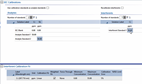
The left side of the IEC page features parameters relating to Analytes (unless 'Use calibration standards as analyte standards' has been selected, in which case Analyte parameters are grayed out and inaccessible). The right side displays parameters relating to Interferent solutions.
 |
If a worksheet contains results, you can only modify some parts of the IEC page. |
 |
This video describes how to setup and run a method with IEC enabled. This example will demonstrate how to remove spectral interferences from Cr on Sb. |
Specify Which Standards to Use as Interferents
Use Calibration Standards as Analyte Standards allows you to use your standard solutions as analyte solutions. Doing so will disable the 'Number of standards' field. Only the Interferent field, table and calibration fit tables will remain editable. If the calibration standards are the same as those used to create the IEC matrix, remeasuring the calibration block immediately after the IEC block is redundant. The option Use Calibration standards for analyte standards develops the IEC matrix and the calibrations without the need to recalibrate again.
|
'Use Calibration standards as analyte standards' is only available when the curve type for all analyte wavelengths on the Standards page is set to Linear. |
Recalibrate Interferents creates new calibration curves which compensates for changes in analyte and interferent response over time. The IEC factors are a function of the interferent sensitivity (Si) and analyte sensitivity (Sj) and are assumed to be constant. Changes in the instrument sensitivity over time, owing to variations in the nebulizer behavior or changes in sample viscosity, are compensated by the recalibration of analyte and interferent standards. Recalibration of interferents occurs during the normal analytical calibration procedure.
When this is selected, 'Use Calibration standards as analyte standards' is not available. In addition, the Interferent Standards column appears in the Concentrations table on the Standards page, and the Interferent calibration fit parameters appear in the Calibration Fit table.
If the calibration standards are the same as those used to create the IEC matrix, remeasuring the calibration block immediately after the IEC block is redundant. The option Use Calibration standards for analyte standards develops the IEC matrix and the calibrations without the need to recalibrate again.
|
When Recalibrate interferents is selected, ensure that standard concentration(s) for the interferent element(s) are defined on the IEC page and that the standards with interferents are selected on the Standards page. |
Interferents can be recalibrated as part of an analyte (re)calibration.
To recalibrate interferents:
- Select Enable IEC on the Configuration page.
- Select Recalibrate interferents on the IEC page. Enter in all standards concentrations that will be used to calculate the IEC factors.
- Enter the analyte and interferent concentrations of the standards on the Standards page, ensuring that each interferent element has a concentration defined in at least one standard. Select the desired standards that include interferents in the 'Interferents Standards' column (if a standard contains an interferent this will be automatically selected by default).
When ‘Recalibrate interferents’ and ‘Calibration every (samples):’ are both selected, the IEC interferent wavelengths get ‘resloped’ when a calibration block gets measured.
IEC factors are calculated from analysis of the solutions defined in Step 2. These factors are then used for all IEC corrections through the run, including after recalibrating analytes and interferents.
To use existing IEC factors, deselect IEC Solutions on the Analysis page. Enter the IEC factors into the IEC factors table. If you opened the worksheet from a template that already had IEC factors calculated, they will appear in the IEC factors table.
Tell me more about Recalibrate interferents.
Interferent Calibration Fit
This table is not available when Recalibrate interferents is selected.
All of the numerical fields in this table (except those grayed out) can be edited directly by clicking the cell and typing in the new value.
Calibration Fit
Linear provides a least squares straight line of best fit in the Intensity vs. Concentration domain. Linear fit is the only option available.
Tell me more about linear, rational and quadratic equations.
Weighted Fit
Select this check box to apply statistical weighting when calculating best fit to the data. Selecting this weights the points of the calibration curve so that those with less error have a higher weighting. The line is then constructed so that it will be closer to the points with higher ratings. Weighted fit is recommended as it allows you to control for errors, by making them smaller where the signal is most accurate.
Tell me more about weighted fit.
Through Blank
Select this check box to force the calibration to fit through the blank signal.
 |
The calibration is forced through the origin if a blank is edited out or is not selected as a part of the calibration. |
|
If the calibration has a non-zero minimum concentration defined, do not select 'Through Blank' for that wavelength, or the origin is used to calculate the line of best fit in the calibration. |
Tell me more about through blank.
Minimum Concentration/Added
Enter the lower limit for which the calibration is valid. This value is usually set to zero, however, the field can be edited. If a sample result is less than the minimum concentration, it is defined as being Underrange. The minimum concentration is editable during a run.
Maximum Concentration/Added
Enter the upper limit for which the calibration is valid. This value is determined by taking the highest concentration value for a line and multiplying it by 110%. For example, if the highest concentration value is 30.0000, the maximum concentration will be 33.00000 (30.0000 x 110%). If a sample result is greater than the Maximum Concentration, it is defined as being Overrange. The field can be edited. The maximum concentration is editable during a run.
Reactive Dilution Trigger
When IEC wavelength concentrations exceed the entered limit during sample analysis, reactive dilution is triggered. Click here for more information.
Calibration Error
Enter the maximum deviation of any standard point from the calibration. Checks each point on the calibration curve to determine how far individual points deviate from the calibration line (of best fit). If the Calibration Error is larger than specified, then it is deemed a failure. All solutions subsequent to the calibration curve will show 'uncal' as the concentration and the calibration curve will not be displayed. The calibration error is editable during a run.
See also: